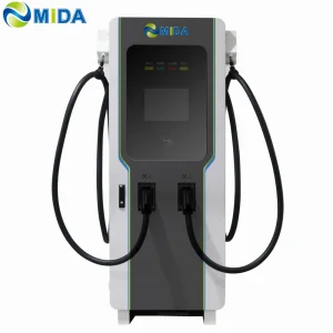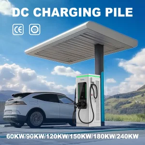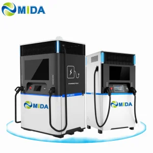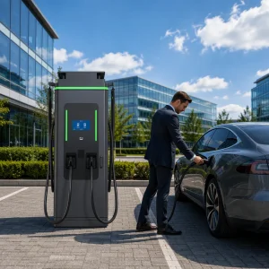
Explore our tier-one lineup of DC Fast Chargers and integrated Battery Energy Storage Systems designed for demanding commercial profiles.
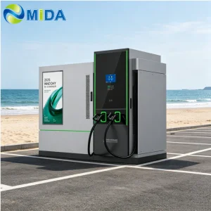
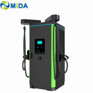
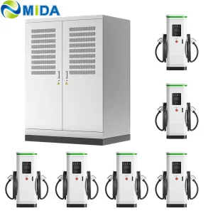
As the global automotive industry experiences an unprecedented shift toward zero-emission passenger and commercial transport, public charging infrastructure must evolve beyond slow AC trickle charging. The 180kW DC Fast Charger represents the "golden mean" of current distribution-grid planning. It balances utility impact, thermal design costs, and charge duration, making it a critical asset for operators worldwide.
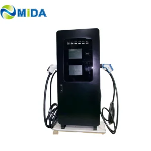
Operating at 180kW, a dual-port fast charger can replenish an average passenger vehicle battery from 20% to 80% state-of-charge (SoC) in approximately 15 to 20 minutes. Crucially, when configured with dynamic load balancing, a single 180kW unit can charge two vehicles simultaneously at 90kW each. This maximizes charge-port throughput and capital expenditure (CAPEX) utility for commercial charging plazas, fleet depots, and highway transit zones.
In Europe, the Alternative Fuels Infrastructure Regulation (AFIR) mandates minimum target power outputs for light-duty vehicle charging hubs along key trans-European networks (TEN-T). In North America, the National Electric Vehicle Infrastructure (NEVI) formula program provides billions of dollars to build out high-power charging corridors, requiring reliable, highly efficient DC power configurations.
Consequently, operators demand systems that not only deliver high power output but also guarantee continuous maximum output under hot summer conditions without derating. This is where high-quality Chinese manufacturers step in. By leveraging robust domestic power-electronics supply chains, they provide cost-efficient, resilient, and highly certified systems that meet international safety codes.
China leads global EV charging station manufacturing due to its comprehensive ecosystem. From raw silicon carbide switches and heavy-duty copper busbars to advanced OCPP control modules and liquid-cooled cable assemblies, all major links of the supply chain reside in industrial hubs like Shenzhen, Shanghai, and Suzhou.
This high concentration of resources allows leading companies, such as the MIDA Group, to execute rapid R&D cycles, customize designs for specific markets (such as integrating advertising screens, RFID payment systems, and battery storage), and offer rigorous electrical testing. When selecting a manufacturer, international buyers must verify structural compliance, quality control measures, and international certifications (such as CE, ETL, CB, UKCA, and UL).
Shanghai Mida Cable Group Ltd. operates through three highly specialized, wholly owned subsidiaries: Shanghai Mida EV Power Co., Ltd., Shenzhen Mida EV Power Co., Ltd., and Shanghai Mida New Energy Co., Ltd.
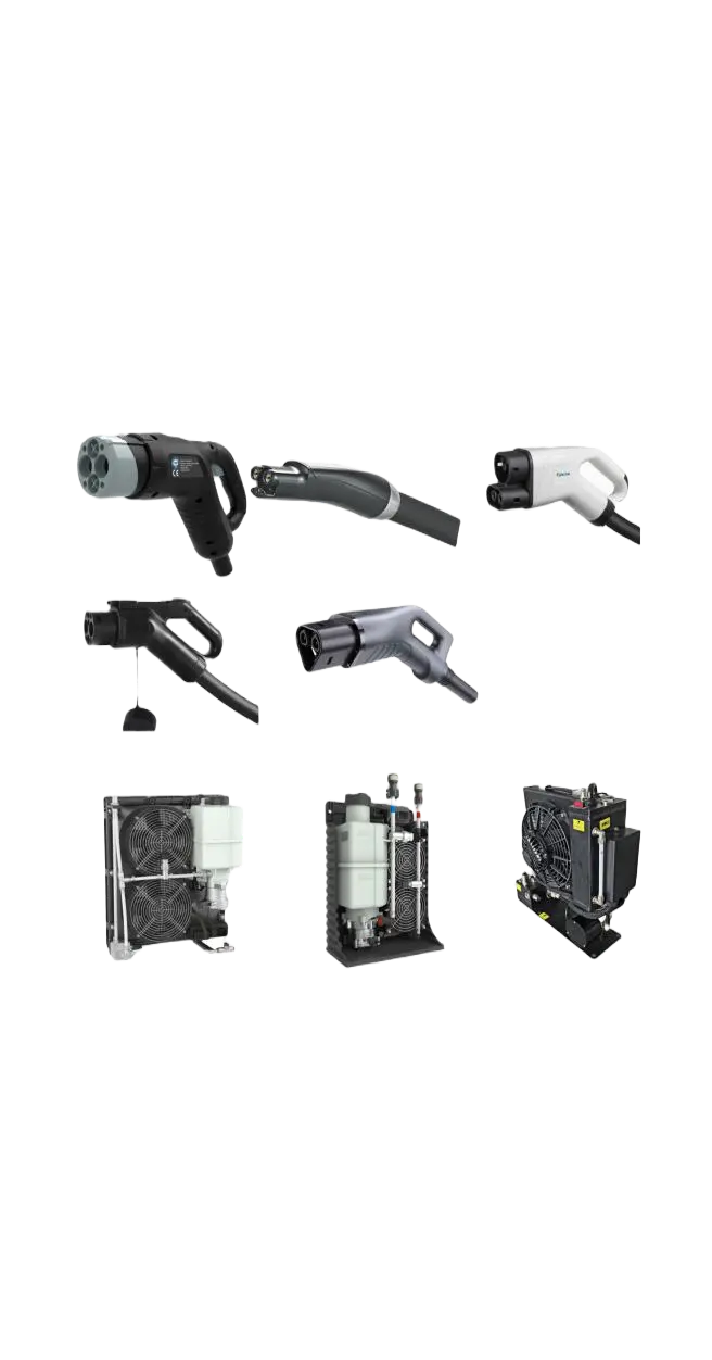
Mida Cable designs and manufactures a comprehensive, world-class catalog of EV charging cables. This includes standard 16A to 80A J1772 cables, 16A to 63A IEC 62196-2 Type 2 cables, and high-performance DC fast charging cables. Our DC options include CCS1 (80A–500A), CCS2 (125A–1000A), CHAdeMO (125A–300A), GB/T (200A–1000A), and state-of-the-art NACS connectors rated from 250A to 600A.
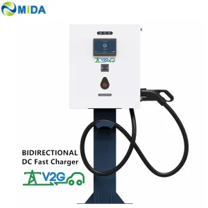
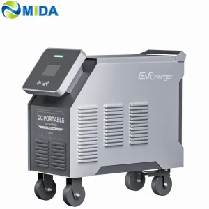
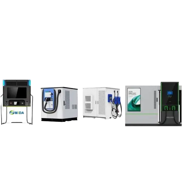
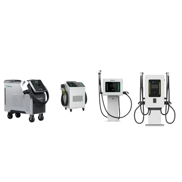
MIDA EV Power produces a full lineup of EV charging stations, ranging from 7kW to 50kW mobile chargers and 3.6kW to 7.2kW portable DC chargers, up to high-capacity 360kW to 1440kW split-type DC fast chargers, 20kW to 50kW wall-mounted DC units, and 60kW to 480kW floor-standing DC fast charging stations.
MIDA New Energy specializes in the R&D of core EV charger components, including 20kW to 60kW standard power modules, 40kW to 125kW liquid-cooled modules, and 20kW to 62.5kW bidirectional/V2G (Vehicle-to-Grid) power conversion systems.

Engineered to meet international industrial standards and optimized for high-power electric vehicle fleets.
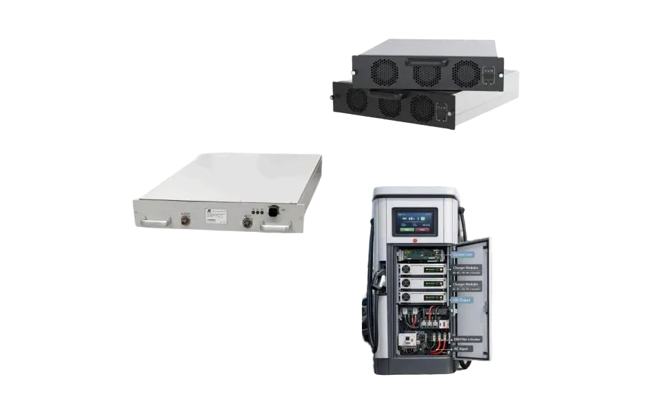
Engineering an industrial-grade 180kW DC charger requires strict design discipline across three subsystems: power conversion, thermal mitigation, and communication. High-power charging networks require high efficiency, low standby losses, and maximum uptime.
Modern 180kW cabinets utilize a multi-module architecture. Rather than relying on a single 180kW converter, manufacturers bundle multiple modular power units (such as six 30kW modules or four 45kW modules) inside a single cabinet. This design approach offers two key advantages:
First, it provides built-in redundancy. If one power module fails, the control board isolates it, allowing the charger to continue operating at reduced capacity (e.g., 150kW or 135kW) rather than going offline entirely. Second, it optimizes the efficiency curve. Because efficiency drops under very low loads, the system dynamically switches off modules when a vehicle charges at a lower power demand, keeping the remaining modules operating at their peak efficiency points.
Did you know? Transitioning from traditional silicon IGBTs to Silicon Carbide (SiC) MOSFETs reduces switching losses by up to 50%, enabling higher switching frequencies. This translates to smaller magnetic components, lighter weight, and system efficiencies exceeding 96.5%.
High-traffic charging stations rarely charge a single vehicle at maximum power all day. A 180kW dual-gun charger must allocate power dynamically between both outlets. When two vehicles plug in simultaneously, the system uses digital communication (via the CAN bus or Ethernet) to query each vehicle's Battery Management System (BMS).
If Vehicle A requests 120kW and Vehicle B requests 60kW, the charger configures its internal module matrix to match this demand. As Vehicle A's charging speed slows down, the power module switches outputs to Vehicle B, optimizing charging speeds for both users and minimizing wait times at the station.
Sustaining a 180kW continuous load generates significant heat. Standard air-cooled chargers use internal variable-speed fans to draw air through dedicated ducts. To prevent dust, moisture, and salt spray from corroding the electronic components, manufacturers seal the electronics in an IP54 or IP55 enclosure with separate cooling channels.
For higher output ratings (such as 360kW to 600kW), manufacturers transition to liquid-cooled systems. Here, a cooling liquid circulates through the charging cables and connectors, allowing the system to run cooler and use thinner, lighter, and more flexible cables that are easier for users to handle.
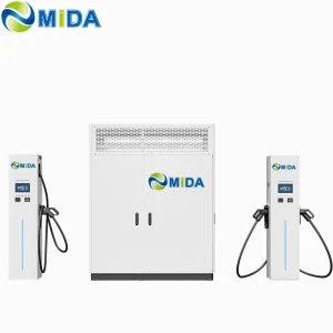
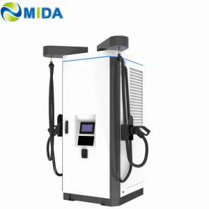
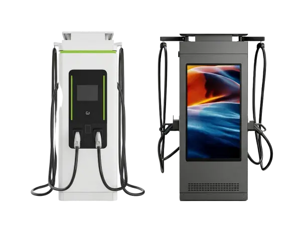
We provide a comprehensive selection of form factors tailored for diverse local site layouts:
Customized high-power charging architectures designed to meet the demands of fleet hubs, retail spaces, and green energy microgrids.
Fleet operations demand high uptime and structured charging. A 180kW configuration allows bus and truck operators to charge vehicles overnight or during driver shift changes. Integrated with telematics, these systems optimize charging schedules based on utility rate structures (such as peak shaving), lowering operational costs.
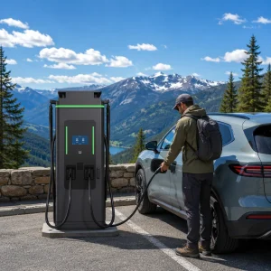
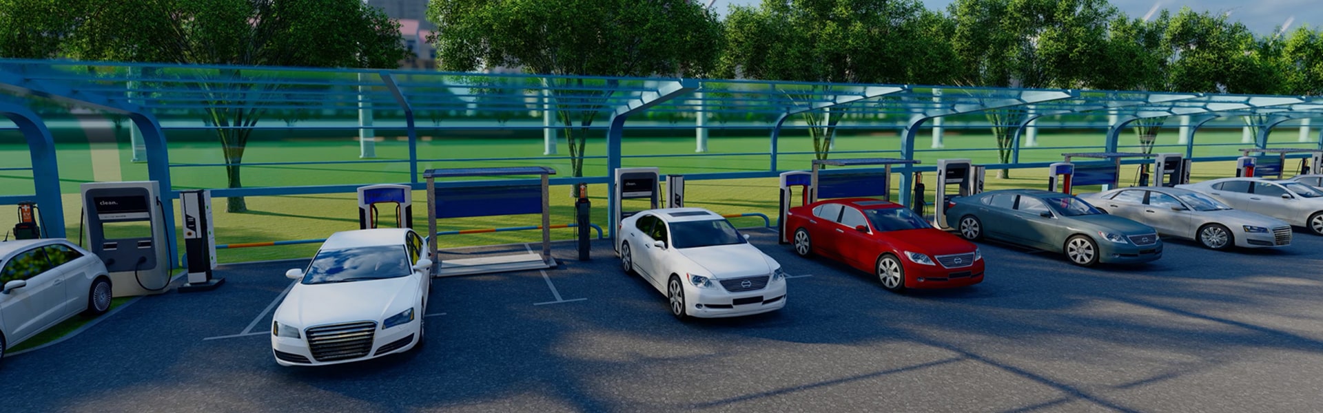
For shopping malls, hotels, and highway rest areas, 180kW chargers attract high-value EV drivers. Integrating OCPP 1.6J or 2.0.1 allows retail operators to connect chargers to third-party billing networks, run marketing campaigns via on-screen advertisements, and collect parking fees during charging sessions.
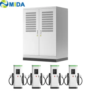
In areas with limited grid capacity, adding battery storage (BESS) and solar PV arrays provides a reliable high-power charging solution. The battery storage system discharges during peak charging demands to prevent high demand charges, recharging later during low-tariff hours or from solar generation.
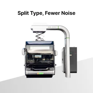
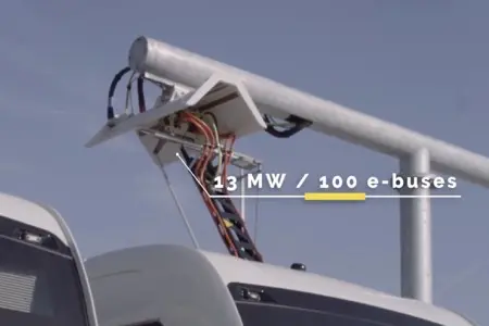
Stay updated on the latest technological advancements in heavy-duty transit charging and pantograph systems.

Expert technical answers to common questions about deployment, compliance, and operation.
Discover our heavy-duty and liquid-cooled fast chargers, built for heavy transport, transit buses, and high-volume commercial fleets.