Engineered for ultra-fast response, utility stability, and reliable power distribution across diverse commercial and transport scenarios.
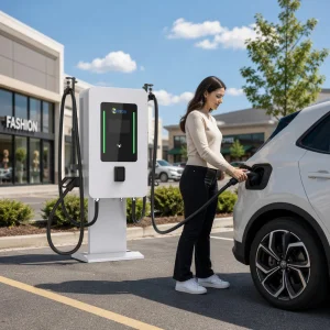
Shanghai Mida Cable Group Ltd. operates through its wholly owned subsidiaries: Shanghai Mida EV Power Co., Ltd., Shenzhen Mida EV Power Co., Ltd., and Shanghai Mida New Energy Co., Ltd.
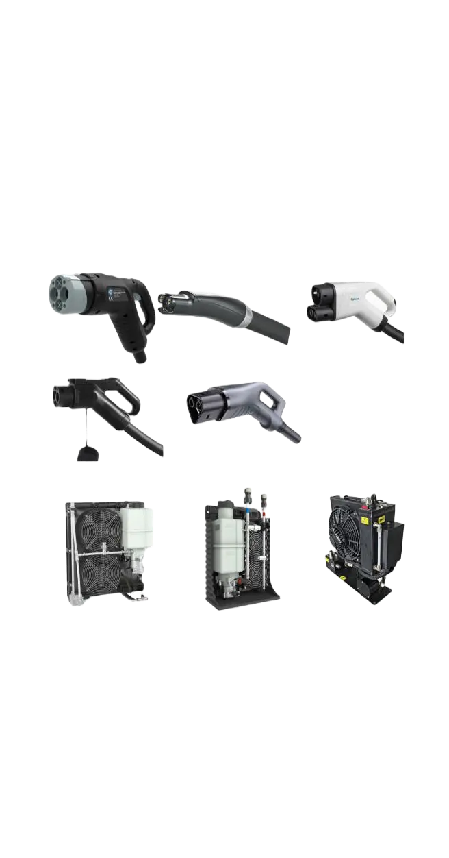
Mida Cable manufactures a comprehensive range of EV charging cables, including 16A–80A J1772 cables, 16A–63A IEC 62196-2 Type 2 cables, and DC fast charging cables: CCS1 (80A–500A), CCS2 (125A–1000A), CHAdeMO (125A–300A), GBT (200A–1000A), and NACS connectors (250A–600A).
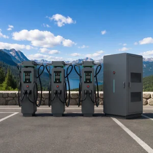
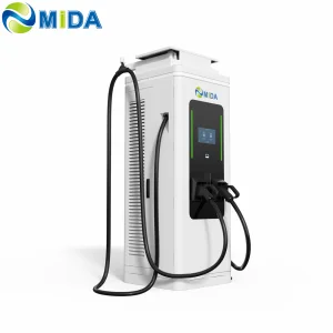
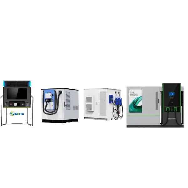
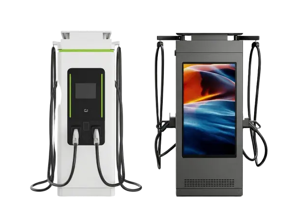
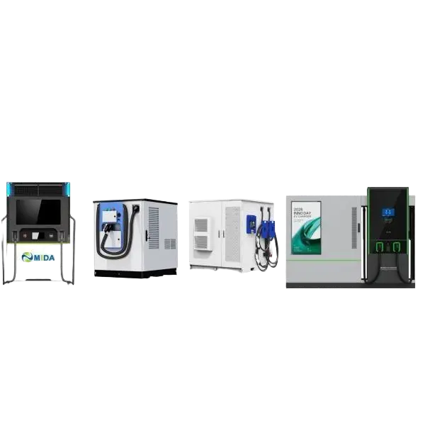
MIDA EV Power produces a full lineup of EV charging stations, such as 7kW–50kW mobile chargers, 3.6kW–7.2kW portable DC chargers, 360kW–1440kW split-type DC fast chargers, 20kW–50kW wall-mounted DC chargers, and 60kW–480kW floor-standing DC fast charging stations.
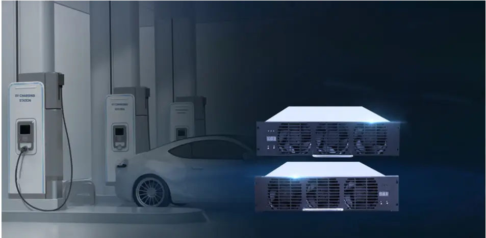
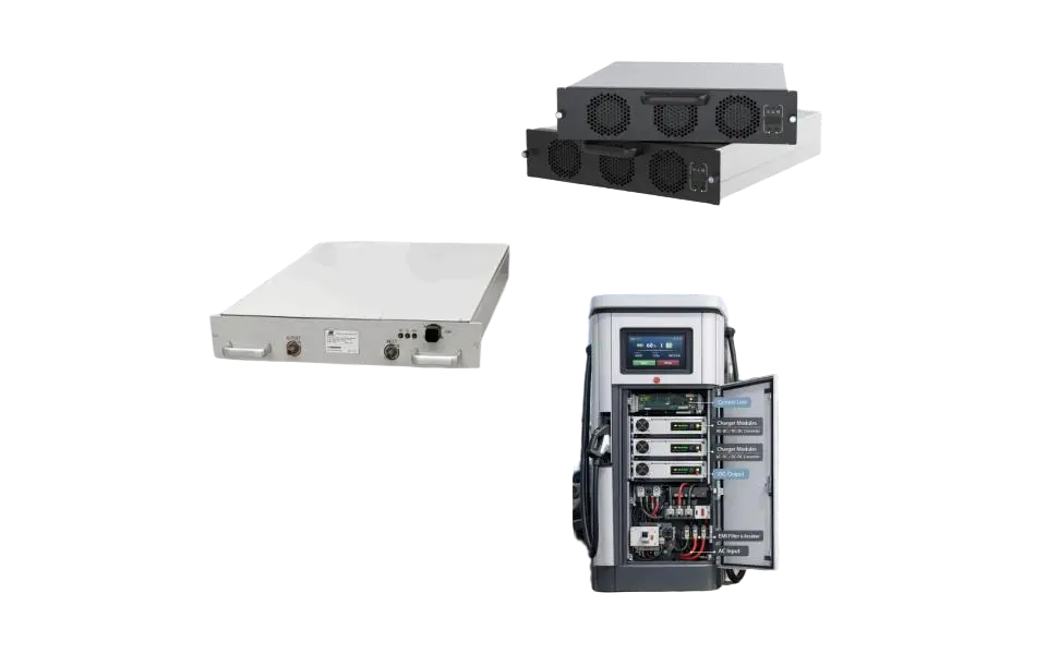
MIDA New Energy specializes in EV charger power modules, offering 20kW–60kW standard modules, 40kW–125kW liquid-cooled modules, 30kW–62.5kW bidirectional modules, and 20kW–45kW V2G charging modules.

High-performance charging stations customized for commercial networks, smart municipalities, and heavy-duty logistics centers.
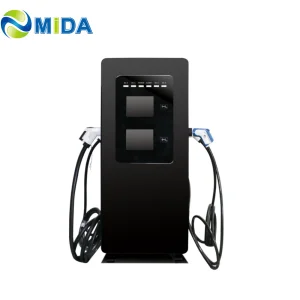
7kW | 20kW | 30kW | 40kW | 60kW | 80kW
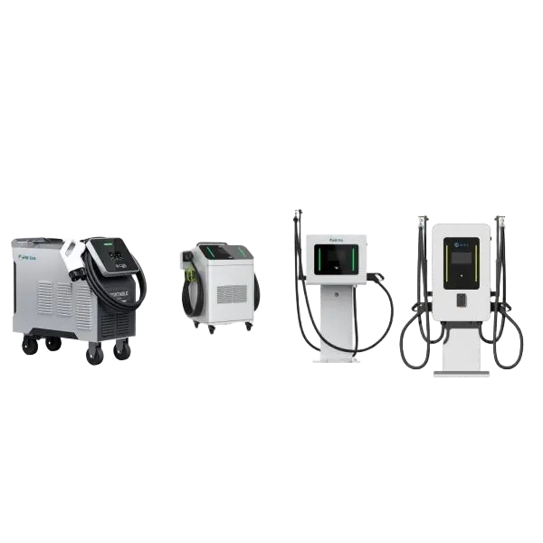
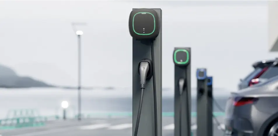
Perfect for corporate offices, municipal parking spots, and destination locations requiring compact footprint and reliable thermal properties.
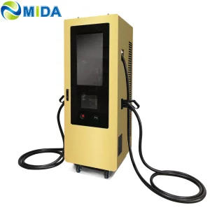
View Details60kW-480kW | 360kW-1440kW
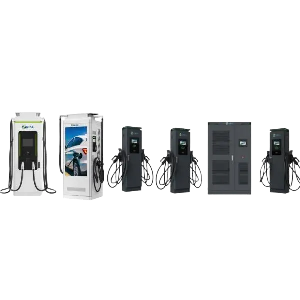
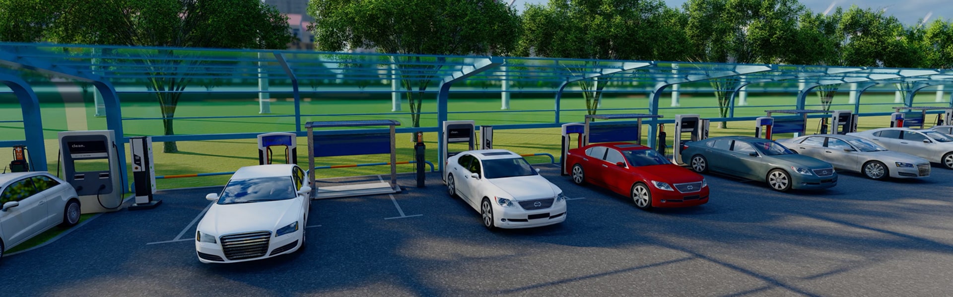
Engineered for highway charging corridors, commercial depots, and high-frequency urban hubs requiring rapid energy replenishment.
View Details60kWh | 261kWh | 418kWh | 625kWh | 2MkWh
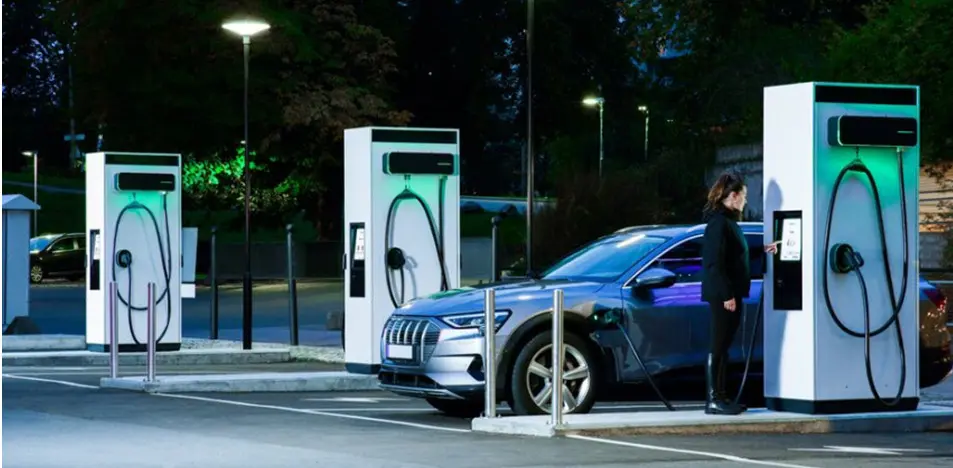
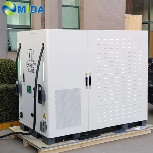
Unlocking extreme charging rates without substantial grid upgrade costs. Built-in energy storage protects distribution grids from peak demand peaks.
View DetailsA technical exploration of global grid integration, thermal management optimization, and the economic benefits of co-locating energy storage systems.
The global transportation sector is undergoing a profound paradigm shift. This transition from fossil-fuel internal combustion engines to electrified drivetrains is placing unprecedented demands on electric vehicle supply equipment (EVSE) networks. In major economic corridors like North America, Europe, and the Asia-Pacific region, charging systems are no longer viewed as peripheral amenities. Instead, they are regarded as critical utility-integrated infrastructure. High-capacity commercial charging networks must handle varied duty cycles while maintaining grid resilience and mitigating peak demand penalties.
Currently, commercial and industrial EV charging operators encounter substantial challenges: grid capacity limitations, high installation costs, complex permitting cycles, and thermal losses at high power levels. To solve these problems, manufacturers must deliver robust, versatile architectures that support multiple standards (CCS1, CCS2, CHAdeMO, GB/T, NACS) and incorporate active safety features. The transition to higher power levels is driven by heavy-duty transportation (Class 8 commercial trucks, municipal transit buses) and premium passenger electric vehicles. These platforms need fast charging solutions that can add hundreds of miles of range in under 15 minutes.
Regulatory bodies are accelerating this shift by mandating minimal distances between charging stations and enforcing high reliability requirements. For instance, the United States' National Electric Vehicle Infrastructure (NEVI) formula program requires uptime exceeding 97% for all federally funded ports. In Europe, the Alternative Fuels Infrastructure Regulation (AFIR) establishes strict requirements for charging capacity along key transport corridors. Commercial charging operators need partners who can supply reliable, certified systems and offer deep engineering support to meet these strict compliance standards.
To charge vehicles faster without increasing connector weight or thickness, the industry is moving from forced-air cooling to active liquid cooling. Charging cables operating above 350 Amperes generate high thermal loads because of resistive losses in the copper conductors. Liquid cooling systems pump dielectric fluids or water-glycol mixtures through the cable and connector. This process controls temperatures, allowing safe, continuous operation at up to 1000 Amperes.
Simultaneously, the integration of Battery Energy Storage Systems (BESS) at the charger site has emerged as a key strategy to resolve grid capacity issues. A BESS-buffered EV charger functions by drawing power from the local distribution grid at a low, continuous rate, storing it in high-density lithium-ion battery banks, and discharging it at high rates (up to 400kW or more per vehicle) during active charging sessions. This setup offers several advantages:
Designing a universal charging solution is not practical because different applications have unique requirements:
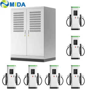
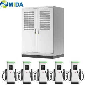
These installations require maximum power delivery, dynamic power allocation, and high durability. High-power split-type DC charging stacks, ranging from 360kW to over 1000kW, are the industry standard for these locations. In these systems, a central power unit contains the conversion modules and dynamically routes power to individual user terminals. This approach optimizes efficiency and reduces vehicle charging times.
For city buses and commercial distribution fleets, charging schedules are highly structured. Systems must support overnight depot charging using automated overhead pantographs or heavy-duty connectors. These operations rely on intelligent energy management systems to sequence charging cycles. This process ensures all vehicles are fully charged before their shifts begin while minimizing total electricity costs.
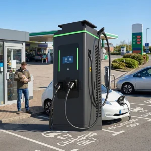
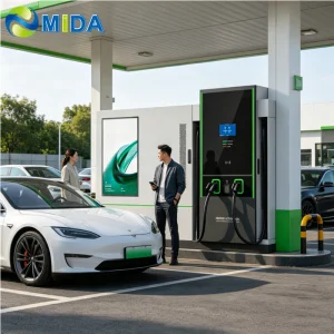
These environments benefit from integrated advertising charging stations (60kW to 240kW) with dual CCS or NACS connectors. These dual-purpose units provide fast charging for customers while generating additional revenue through high-definition digital advertising displays. They require OCPP 2.0.1 compliance to connect with payment processors, mobile apps, and ad network management systems.
MIDA Group has established a vertically integrated manufacturing model to address the complexities of EVSE deployment. By manufacturing every critical component in-house—including cables, connectors, power modules, liquid-cooling systems, control boards, and complete structural enclosures—we ensure high levels of compatibility, performance, and quality control.
This level of integration is essential for next-generation charging platforms. For example, our liquid-cooled split DC charging hub uses proprietary power modules, specialized liquid-cooled cables, and custom control software. Because we design and manufacture the entire system, we can optimize the thermal interface between the connector and the cooling unit. This results in reliable heat dissipation, minimal energy loss, and extended component lifespans in demanding commercial applications.
The EVSE industry is evolving rapidly, driven by three key technological shifts:
For heavy-duty freight transport, current fast-charging standards are insufficient. The upcoming MCS standard is designed to support operating voltages up to 1250 Volts and currents up to 3000 Amperes. This allows for a maximum charging capacity of 3.75 Megawatts. Developing components for these power levels requires advanced engineering in cable design, busbar systems, and active liquid-cooling technologies.
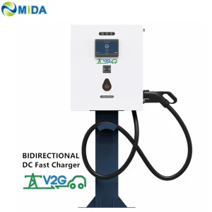
Vehicles are transforming from energy consumers into mobile energy storage assets. Bi-directional V2G charging systems allow fleet operators to supply power back to the grid during peak demand periods or use vehicle batteries to back up facility loads during blackouts. This technology requires bidirectional AC/DC power conversion modules and compliance with communication protocols like ISO 15118-20.
Modern charging hubs generate significant amounts of telemetry data. By applying machine learning models to monitor parameters like temperature, voltage stability, and insulation resistance, operator systems can detect potential issues before components fail. Additionally, AI algorithms can optimize charging rates based on weather forecasts, utility prices, and vehicle schedules. This improves efficiency and reduces operating costs.
High-quality components and modules engineered to meet strict international standards, including TUV, ETL, and RCM.
Technical discussions regarding pantograph connections, installation parameters, and electric bus charging.
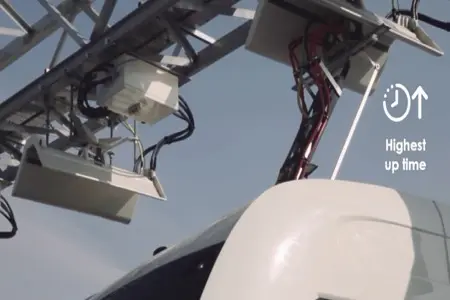
What are the advantages of an e-bus pantograph dome? In contrast to classic plug-in charging systems, e-bus pantograph connections support automated charging for large transport fleets...
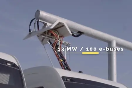
How long does it take to charge with an e-bus pantograph? The charging time depends on the battery capacity, the grid delivery parameters, and the maximum power rate...
How to Install the Pantograph Up Charger System Dome for Electric Bus. Installing a "Pantograph Up" system requires precise positioning and strict compliance with local grid codes...
Answers to common engineering and deployment questions from commercial developers, fleet operators, and utility managers.
Active liquid-cooled systems use a dielectric fluid or a water-glycol mixture to manage heat generated in the power cables and connectors. This cooling capacity allows chargers to operate at up to 1000 Amperes without causing safety hazards. Air-cooled systems are simpler to design but are generally limited to around 200–350 Amperes. Beyond this range, air-cooled cables become too heavy and stiff for users to handle. Liquid cooling also extends component life by keeping internal temperatures low and stable.
BESS-buffered chargers store energy during periods of low demand and release it at high discharge rates when vehicles connect. This setup offers three key advantages: first, it avoids utility peak demand charges; second, it allows fast charging on grids with limited capacity without needing expensive infrastructure upgrades; and third, it provides emergency backup power during grid outages, helping to stabilize the local network.
OCPP 2.0.1 offers significant security and operational upgrades compared to older versions like OCPP 1.6J. It includes advanced device management features, letting operators monitor and configure chargers remotely. It also supports ISO 15118 protocols for secure transaction handling and "Plug & Charge," improving the user experience while strengthening cybersecurity protections.
V2G allows bidirectional power flow, enabling vehicle batteries to discharge electricity back into the grid or feed a local facility during peak demand periods when rates are highest. For fleet operators, this can generate new revenue through demand response programs or reduce utility expenses, lowering the total cost of ownership for commercial electric vehicles.
Installing a "Pantograph Up" system requires precise physical alignment between the bus roof contacts and the overhead dome. The installation also demands high-power grid integration (often above 450kW) and automated control software to handle connection sequences safely. These systems must operate reliably in varied weather conditions, requiring robust environmental sealing and active safety monitoring.
Engineered to support global communication protocols and power standards, including AFIR-compliant public charging setups.