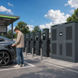
Premium DC Wallboxes, Solar Integrated Chargers, and Liquid-Cooled Infrastructure Engineered for Uncompromised Charging Reliability
Shanghai Mida Cable Group Ltd. operates globally through its dedicated, wholly-owned specialized subsidiaries: Shanghai Mida EV Power Co., Ltd., Shenzhen Mida EV Power Co., Ltd., and Shanghai Mida New Energy Co., Ltd. Together, we deliver end-to-end, high-performance powertrain interface components and structural hardware for the modern electric vehicle charging ecosystem.
Mida Cable designs and manufactures a comprehensive, heavy-duty range of EV charging cables, including 16A–80A J1772 standard cables, 16A–63A IEC 62196-2 Type 2 cables, and specialized DC Fast Charging cables supporting global standards: CCS1 (80A–500A), CCS2 (125A–1000A), CHAdeMO (125A–300A), GB/T (200A–1000A), and high-demand NACS connectors (250A–600A).
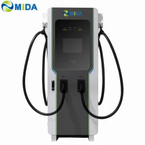
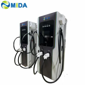
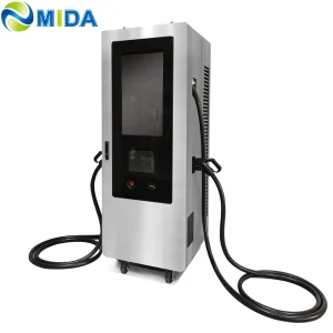
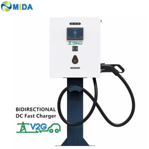
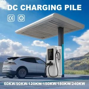
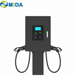
MIDA EV Power focus on complex system integrations, delivering advanced charging infrastructures like 7kW–50kW mobile charging units, 3.6kW–7.2kW portable DC fast systems, 360kW–1440kW high-capacity split-architecture charging matrices, 20kW–50kW space-saving wall-mounted DC units, and robust 60kW–480kW floor-standing charging systems.
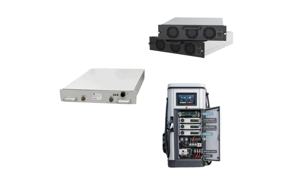
MIDA New Energy focuses on the technology at the core of energy conversion, specializing in high-efficiency EV charger power modules. Our portfolio includes 20kW–60kW standard air-cooled modules, 40kW–125kW liquid-cooled modules, 30kW–62.5kW bidirectional modules, and 20kW–45kW specialized V2G power modules.

Reliable commercial-grade solutions built for fleet depots, heavy industry, public networks, and smart energy storage facilities.
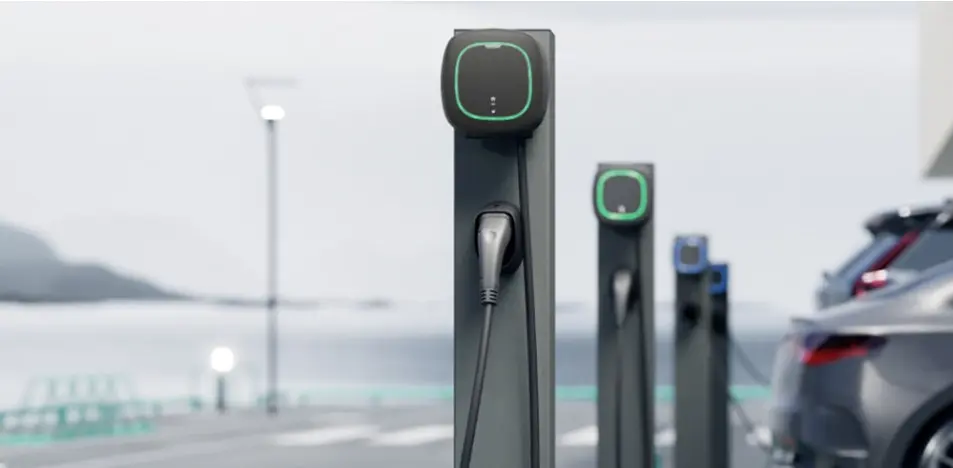
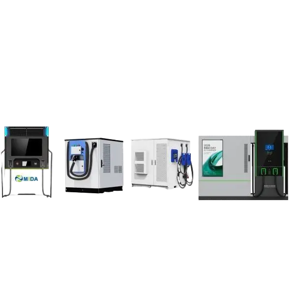
Compact high-speed DC power delivery systems starting from 7kW to 80kW. Optimal for workspace parking, vehicle repair hubs, and dynamic fleet charging deployment.
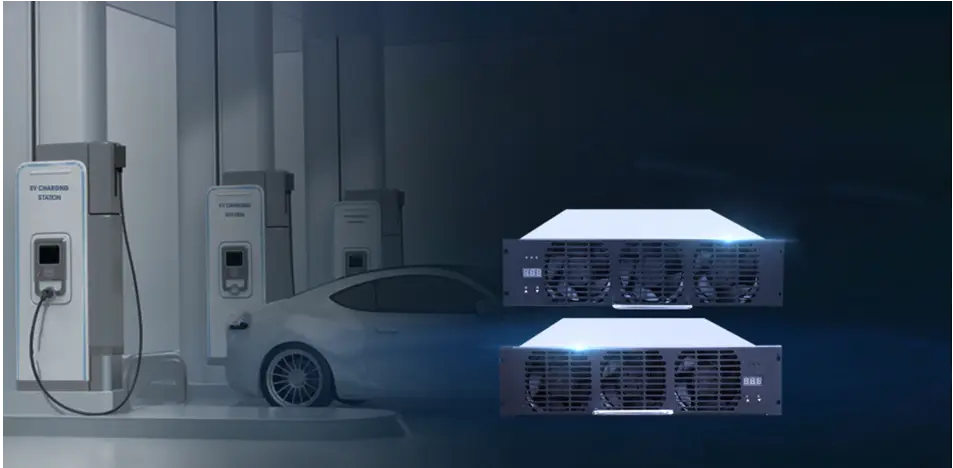
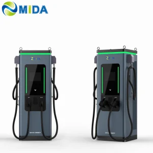
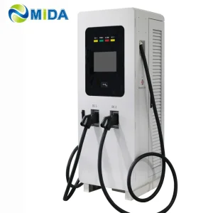
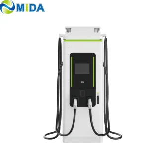
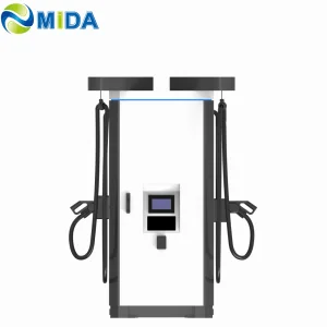
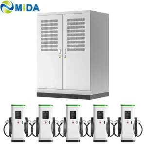
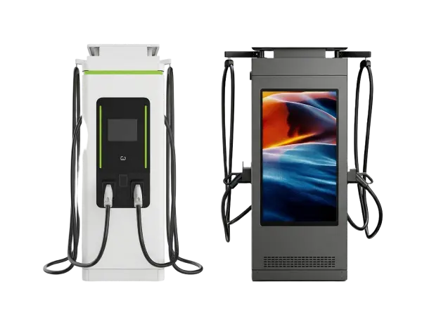
From 60kW dual-port dispensers to 1440kW split-architecture liquid-cooled megawatt hyperchargers designed for high-throughput heavy logistics and bus transit corridors.
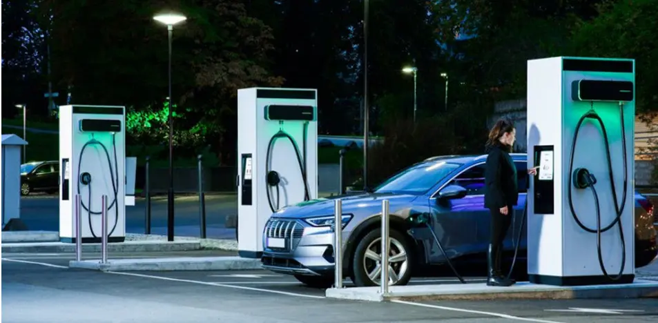
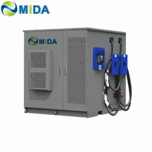
Combine high-capacity energy storage (60kWh up to 2MWh+) with integrated fast chargers. Buffer local grids, shave peak demand charges, and integrate local photovoltaics.
The global heavy electric vehicle landscape is undergoing a massive shift towards electrification. Standard high-power charging (HPC) setups operating between 150kW and 350kW are no longer sufficient for class 8 shipping trucks, electric mining haulers, and long-range municipal bus fleets. The industry is rapidly pivoting toward Megawatt Charging Systems (MCS), capable of handling currents up to 3,000A at 1,250V. This shift requires factories to completely redesign core hardware, moving from air-cooled systems to advanced closed-loop liquid-cooled thermal dissipation matrices. By keeping connector temperatures below critical operating levels, operators can achieve safe continuous output without thermal throttling.
One of the largest hurdles to deploying massive ultra-fast charging hubs is local grid capacity. Deploying multiple 350kW chargers can quickly exceed the limits of local distribution transformers. Demanding upgrades from regional utility providers often involves multi-year timelines and high capital expenditures. Integrating Battery Energy Storage Systems (BESS) directly into the charging architecture solves this challenge. High-density lithium iron phosphate (LFP) chemistry buffers grid power, storing energy during periods of low activity and discharging it during high-load charging sessions. This hybrid topology reduces expensive peak-demand charges and ensures operational reliability even in grid-constrained regions.
Global procurement teams must navigate complex, localized regulatory standards when deploying charging infrastructure. In North America, systems must comply with UL 2202 and ETL safety certificates, alongside the growing adoption of the North American Charging Standard (NACS/SAE J3400). In Europe, compliance with CE, TÜV, and IEC 61851 / IEC 62196 is non-negotiable. Furthermore, backend operations require strict compliance with communication standards. Operating software must use OCPP 1.6J and OCPP 2.0.1 JSON protocols via secure TLS connections to allow seamless integration with charging network management systems (CNMS). Hardware must support ISO 15118 to enable secure, user-friendly "Plug & Charge" capabilities.
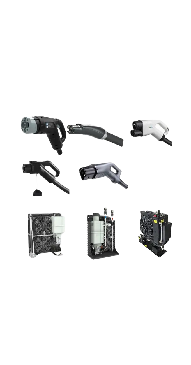
When charging currents exceed 250A, traditional air-cooled cables become too heavy and stiff to handle due to the copper cross-section required. Liquid-cooled charging technology resolves this by circulating a synthetic coolant fluid or water-glycol mixture through dedicated channels inside the cable and connector. This allows for thinner, lighter, and more flexible cables capable of handling up to 1000A continuously. Additionally, modern high-power cabinets utilize liquid-cooled power modules. By isolating active electronics from dust, moisture, and corrosive air contaminants in a sealed enclosure, liquid cooling extends component lifespans by up to 40% compared to traditional forced-air ventilation designs.
Engineered for maximum efficiency, safety, and integration across global energy markets.
Keep pace with global infrastructure updates, engineering developments, and installation best practices.
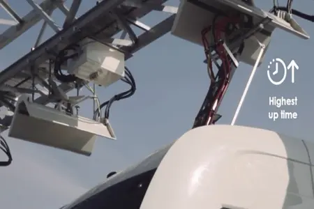
What are the advantages of an e-bus pantograph dome? In contrast to classic plug-in charging systems, e-bus pantograph solutions allow for high-power overhead automated charging during scheduled route stops...
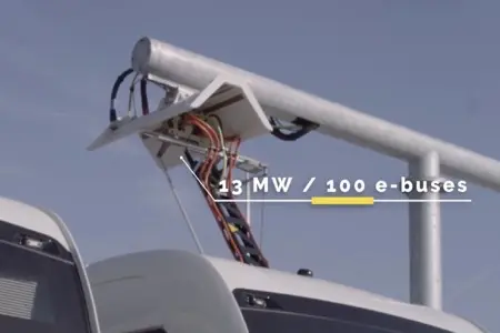
How long does it take to charge with an e-bus pantograph? The charging time depends on the battery capacity and the station's output power. Using high-power overhead charging can recharge local transit fleets in minutes...
How to Install the Pantograph Up Charger System Dome for Electric Bus. Installing a "Pantograph Up" system requires precise spatial engineering, local structural concrete anchorage, and dedicated medium-voltage grid integration...
Answering key technical and regulatory questions for utility operators and global procurement managers.
A: Liquid-cooled systems circulate dielectric fluids or glycol mixtures through the cable and core power modules to manage thermal loads efficiently. This allows the system to support continuous currents of 500A to 1000A without overheating or needing to throttle power output. Air-cooled systems are generally limited to 250A or less to keep cable weights manageable for users. Additionally, liquid-cooled power modules are sealed from the environment, protecting internal electronics from dust, moisture, and corrosive salt air. This extends the service life of components in challenging outdoor environments.
A: Split-architecture chargers separate the main power conversion cabinet from the user dispensers. The power module stack uses intelligent firmware to direct power in granular steps (typically 20kW, 30kW, or 40kW increments) depending on the vehicle's state of charge (SoC) and battery temperature. For example, if a vehicle can only accept 120kW, the system routes exactly six 20kW modules to that dispenser, leaving the remaining capacity available for other vehicles. This improves system utilization, reduces energy waste, and lowers total cost of ownership (TCO) for fleet operators.
A: ISO 15118 defines the digital communication interface between electric vehicles and charging stations. It enables features like "Plug & Charge," where the vehicle identifies itself and handles billing automatically upon connection, removing the need for RFID cards or mobile apps. Crucially, ISO 15118 also supports bidirectional power transfer, which enables Vehicle-to-Grid (V2G) and Vehicle-to-Home (V2H) applications. This allows fleet operators to feed power back to the grid during peak periods, creating new revenue streams.
A: Utility companies charge commercial customers peak-demand fees based on their highest electricity usage in a given period. When high-power EV chargers start up, they create large, sudden power draws. An integrated BESS acts as a buffer by discharging stored energy to support the peak load, keeping the grid connection stable and flat. This peak-shaving capability helps operators avoid expensive demand surcharges, making it possible to install high-speed charging infrastructure in areas with limited grid capacity.
Premium heavy-duty systems engineered for extreme duty cycles, dual-nozzle distribution, and integrated battery energy storage.