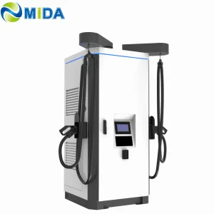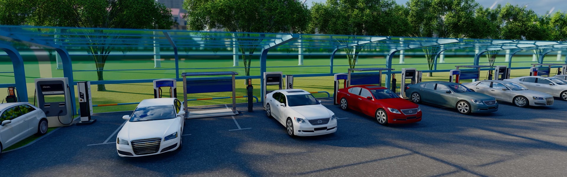
Best 350 kW DC Fast Charger Manufacturer & Factories

Empowering the Global EV Transition with MW-Scale High-Power Charging (HPC) Systems, Solid-State Power Conversion Modules, & Smart Energy Storage Integration.

Welcome to MIDA GROUP

Shanghai Mida Cable Group Ltd. operates through its wholly owned subsidiaries: Shanghai Mida EV Power Co., Ltd., Shenzhen Mida EV Power Co., Ltd., and Shanghai Mida New Energy Co., Ltd. As a pioneer in high-power energy transmission technology, we support international automotive standards across the globe.

Strategic Manufacturing Portfolio:
  • Mida Cable: Produces a comprehensive range of EV charging cables, including 16A–80A J1772, 16A–63A IEC 62196-2 Type 2, and high-performance DC cables: CCS1 (80A–500A), CCS2 (125A–1000A), CHAdeMO (125A–300A), GBT (200A–1000A), and NACS connectors (250A–600A).
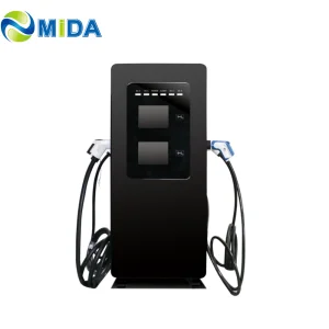
  • MIDA EV Power: Supplies complete EV infrastructure ecosystems, spanning 7kW–50kW mobile chargers, 3.6kW–7.2kW portable DC chargers, 360kW–1440kW split-type DC fast chargers, 20kW–50kW wall-mounted DC units, and 60kW–480kW commercial floor-standing DC stations.
  • MIDA New Energy: Specializes in raw modular components, offering 20kW–60kW standard converter modules, 40kW–125kW liquid-cooled conversion modules, 30kW–62.5kW bidirectional modules, and 20kW–45kW V2G (Vehicle-to-Grid) units.
Mida Group Facility Certifications

Main Product Categories

Industrial-grade components and systems tailored to commercial fleet operations and high-volume public charging corridors.

EV Charging Power Modules

The conversion engine of ultra-fast stations. Features high power factor and efficiency.
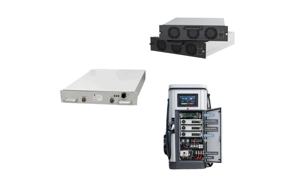
  • 30kW - 80kW AC/DC Conversion Modules
  • 40kW - 125kW Liquid-Cooled Power Modules
  • 20kW - 45kW Bidirectional V2G Power Modules
  • 30kW - 60kW MPPT Solar Charging Modules
Power Module

Liquid Cooling Connectors & Units

Essential dynamic cooling to sustain high amperage continuously without overheating.
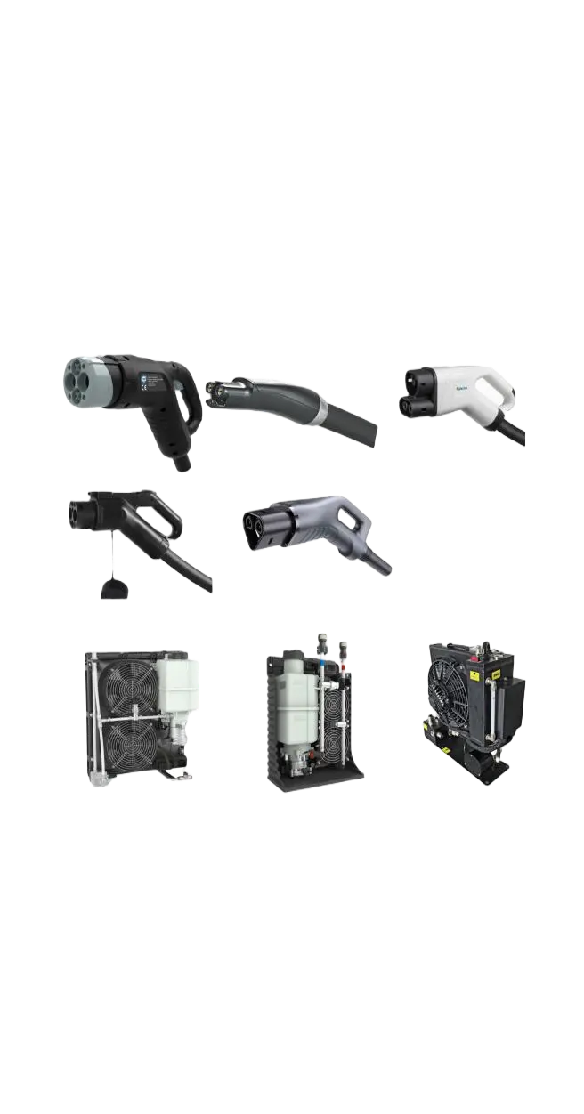
  • 500A - 1000A liquid-cooled CCS1, CCS2 & GBT
  • 250A - 600A NACS & CHAdeMO Connectors
  • 1500A Megawatt MCS & ChaoJi standards
  • 3.5kW - 72kW Integrated Cooling Units for HPC
Cooling Units

DC Fast Charging Stations

Turnkey floor-mounted and split charging structures ready for international integration.
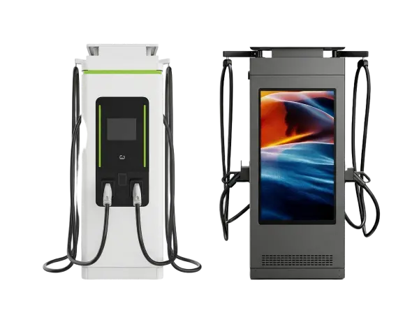
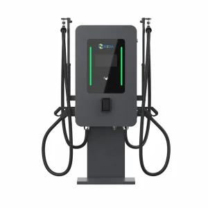
  • 7kW - 60kW Mobile & Wall-Mounted Stations
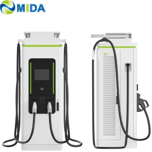
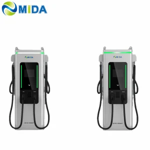
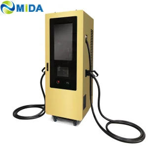
  • 60kW - 480kW Standard Stand-Alone Units
  • 600kW - 1080kW Liquid-Cooled Station Nodes
  • 360kW - 1680kW Split Type Scalable Chargers
DC Stations

BESS Charging Systems

Peak-shaving storage-backed chargers that solve local grid capacity limits.
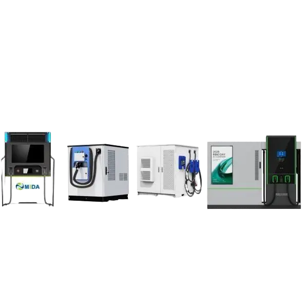
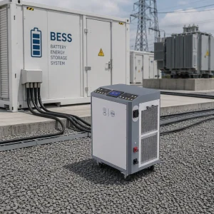
  • 15kW - 480kW Mobile BESS Charging Stations
  • 60kW - 400kW Integrated Battery Charger Piles
  • 65kWh - 200kWh Rescue Charging Trailers
  • 800kWh - 2000kWh MW Solar-BESS Systems
BESS Systems

Deep-Dive Whitepaper: Next-Gen 350 kW DC Ultra-Fast Charging

A comprehensive engineering & procurement framework for charge point operators (CPOs) and fleet infrastructure partners.

1. The Physics of 350 kW High-Power Charging (HPC)

As electric passenger vehicles and commercial trucks adopt 800V and 1000V battery architectures, traditional 50kW and 150kW chargers present a severe bottleneck. A 350 kW DC Fast Charger represents the critical inflection point, capable of delivering up to 350 kilometers of range in under 10 minutes. Achieving this requires managing massive electrical currents—often up to 500A continuously.

In typical charging environments, delivering high current generates thermal resistive losses proportional to the square of the current ($I^2R$). Without active cooling, copper conductors would require a diameter too thick and heavy for average consumers to handle. Thus, modern 350kW systems utilize liquid-cooled charging cables and cooling units that pump dielectric fluid to the connector pins, maintaining the temperature below standard 50°C limits.

2. China Manufacturing Ecosystem Advantages

China has established a massive global lead in EV charging infrastructure manufacturing due to unique structural and vertical integration factors:

  • Integrated Supply Chain: Chinese manufacturers operate in tight clusters (such as Shanghai, Shenzhen, and Jiangsu) where silicon carbide (SiC) semiconductor packaging, copper cable extrusion, and microcontroller programming happen within a 50-mile radius. This reduces raw material lead times from months to weeks.
  • Economies of Scale: Leveraging China's vast domestic network of ultra-fast charging corridors allows manufacturers to test and refine firmware, safety features, and protocol handshakes across millions of charging cycles before exporting hardware globally.
  • Cost-Optimized Engineering: By developing proprietary high-power conversion modules (such as MIDA's 40kW/125kW modules), local factories offer highly competitive total cost of ownership (TCO) without sacrificing regulatory compliance like CE, UL, or PTB MID.

3. Structural Architecture: Integrated vs. Split-Type Chargers

For infrastructure developers deploying 350kW stations, choosing the appropriate structural topology is essential for space constraints and thermal efficiency:

Parameter Integrated DC Fast Charger Split-Type DC Power Stack
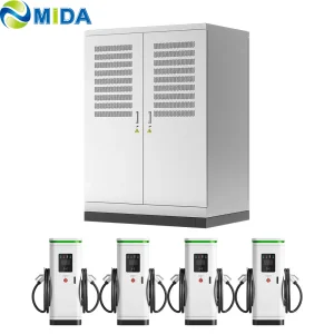
Power Allocation Fixed inside the cabinet (e.g., 2 x 175kW or 1 x 350kW). Dynamic allocation across multiple satellite dispensers.
Footprint Requires larger footprint at the parking bay. Compact dispenser at bay; power stack placed elsewhere.
Thermal Management Self-contained fans or small liquid chillers. Centralized cooling unit housed in the primary power cabinet.
Scalability Limited; upgrading requires replacing the unit. Highly scalable; modules can be added to the central stack.

4. Solving Grid Limitations: BESS-Buffered Charging

Deploying multiple 350kW charging dispensers can put a massive strain on local electrical grids. Many utility grids cannot support multi-megawatt step-down transformers without prohibitively expensive and slow utility upgrades.

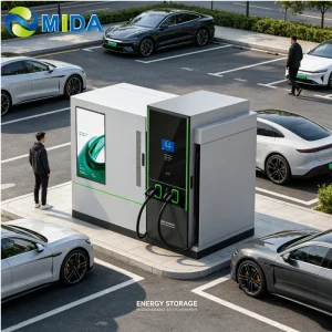
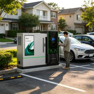
The integration of Battery Energy Storage Systems (BESS) solves this challenge. By pairing a 200kWh to 2MWh battery buffer with solar PV and 350kW chargers, CPOs can draw continuous low power from the grid during off-peak hours and dump stored energy at high rates (350kW+) when an EV plugs in. This process of "peak shaving" reduces demand charges, lowers energy costs, and speeds up deployment.

5. Global Procurement, E-E-A-T Standards, and Regulatory Compliance

Importing high-power charging infrastructure demands strict adherence to international electrical safety regulations. A failure to comply can lead to rejected permits, voided insurance, or catastrophic field failures. CPOs must verify the following standards:

  • Electrical Safety & Listing: UL 2202 and UL 2231 for North American installations; CE LVD/EMC for European territories.
  • Communication Protocols: Full OCPP 1.6J or OCPP 2.0.1 JSON compliance to ensure integration with back-end management software, payment gateways, and vehicle-to-grid (V2G) handshakes under ISO 15118.
  • Metrology & Billing: PTB approval and MID compliance in Europe, ensuring that billing units accurately record energy delivery to the kilowatt-hour.

6. Macro-Industry Solutions & Localized Scenarios

Modern CPOs require tailored configurations depending on their specific operational context:

10 Min
Highway Corridors

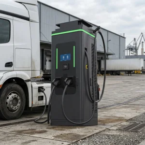
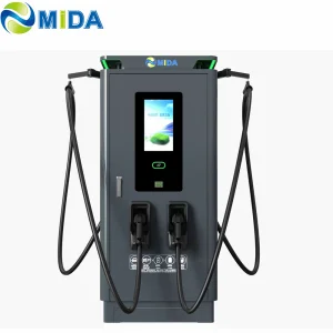
Liquid-cooled dual-gun dispensers maximizing throughput.

99.8%
Transit Fleets

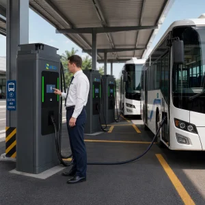
High-uptime overhead pantographs and heavy-duty MCS connections.

Zero
Off-Grid Depot

Solar-coupled BESS mobile trailers providing tactical power.

Frequently Asked Questions

Technical insight straight from our electrical testing engineers.

What is the real-world utility grid requirement for a 350kW DC Fast Charger? +
To deliver a full 350kW output continuously, a station requires a grid connection capacity of at least 380kVA to 400kVA per dispenser to account for conversions, power module losses, and auxiliary systems (such as cooling pumps and LED advertising displays). Most commercial installations deploy a dedicated step-down transformer converting local medium voltage to three-phase 400V or 480V AC.
How does liquid-cooled cable technology prevent thermal runaway in high-amperage systems? +
Liquid-cooled systems circulate synthetic oil or water-glycol mixtures through internal coolant channels surrounding the copper conductors and connector pins. Real-time temperature sensors in the connector communicate with the charger's microcontroller. If temperature thresholds (typically 50-55°C) are exceeded, the system dynamically scales down the amperage to protect the vehicle's battery management system (BMS) and the charger connector.
What is the difference between OCPP 1.6J and OCPP 2.0.1 for fleet management? +
OCPP 2.0.1 offers superior cybersecurity features (secure transport layer security - TLS), advanced diagnostics, and native support for ISO 15118 "Plug & Charge" standard. It also permits more granular reporting on energy usage, smart charging profiles, and bidirectional energy coordination (V2G), which is crucial for modern grid-balancing commercial fleets.
Can standard EVs charge at a 350kW charger without damaging their battery pack? +
Yes. The charging process is fully negotiated by the EV's Battery Management System (BMS). When connected, the vehicle specifies its target voltage and maximum current limit. The 350kW charger adapts its output dynamically. An older 400V vehicle will charge at its standard rate (e.g., 50kW or 100kW) safely, while an 800V vehicle will draw high power safely.
How does energy storage (BESS) integration assist in avoiding high demand charges? +
Peak demand charges are calculated based on the highest energy consumption peak within a utility billing period. Deploying a 350kW charger can cause sudden spikes. Integrating a BESS allows the station to discharge battery power to shave off these demand spikes (peak shaving), drawing from the utility grid at a constant, lower rate instead of a volatile high-power surge.

Corporate Insights & Technological News

Stay updated with research and analysis on zero-emission transit solutions.

Pantograph Up Charger

What are the advantages of an e-bus pantograph dome?

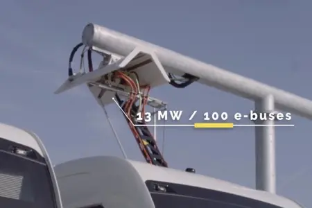
In contrast to classic plug-in charging systems, e-bus pantographs allow automatic, hands-free charging during brief layovers.

Read Full Article →
E-Bus Pantograph Charging

How long does it take to charge with an e-bus pantograph?

Charging times depend on battery capacity and utility supply, typically range from 5 to 15 minutes during route intervals.

Read Full Article →
Installing Pantograph Up Charger

How to Install Pantograph Up Charger Systems

An inside look into structural requirements, transformer links, and alignment sensors for high-power overhead charging setups.

Read Full Article →
Mida Group Advanced Testing Ground