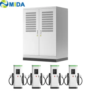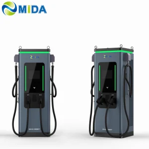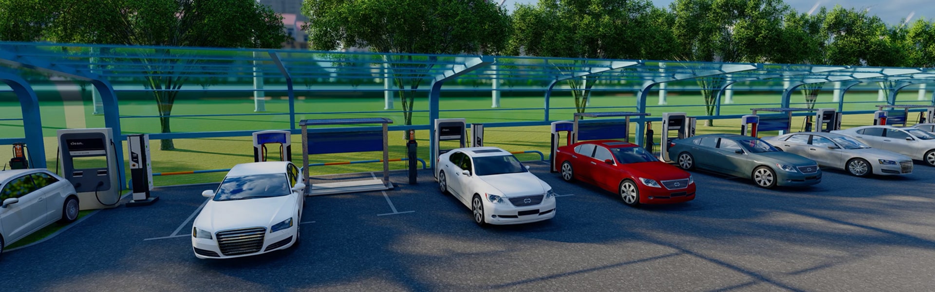
Industrial grade electric vehicle supply equipment designed for high-density public corridors, fleet hubs, and highway fast charging.
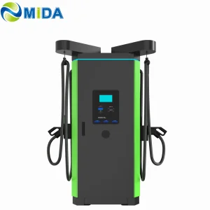
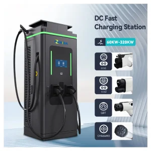
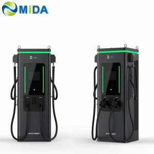
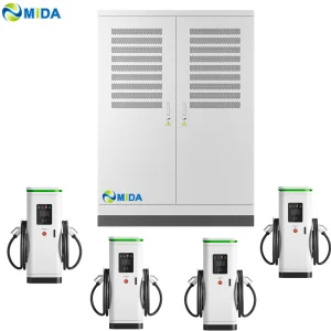
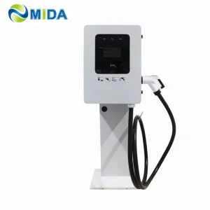

The global EV transition has evolved from early adoption to high-power commercial scale. As modern EV architectures transition to 800V platforms (with next-generation batteries demanding charge rates upwards of 3C to 4C), standard AC and medium-power DC charging units no longer suffice. A 360kW DC Fast Charger stands as the core pivot for ultra-fast highway charging, bus rapid transit system terminals, logistics parks, and public fast-charging hubs.
By providing up to 360 kilowatts of continuous energy, this system splits power output seamlessly across multiple dispensaries, providing optimal energy distribution to maximize throughput. It ensures standard passenger EVs can gain up to 200 kilometers of range in under 10 minutes, directly addressing range anxiety and accelerating public infrastructure investment ROI globally.
Across Europe, North America, and the Asia-Pacific region, grid operator coordination and high-capacity chargers are reshaping commercial fleets. In the European Union, the Alternative Fuels Infrastructure Regulation (AFIR) mandates minimum target outputs for light and heavy vehicle fleets along core TEN-T networks, making high-power chargers (HPC) mandatory. In North America, the National Electric Vehicle Infrastructure (NEVI) program funds the integration of multi-port charging structures demanding high uptime and reliability.
Chinese factories and suppliers have evolved to meet this surge. They offer sophisticated supply chains, high-volume production, and competitive engineering architectures that adhere to stringent global standards. As a result, Chinese 360kW fast charger factories stand out as essential OEM/ODM partners for global utility developers, charge point operators (CPOs), and energy conglomerates.
Intelligently balances power between dual connectors based on vehicle demands, preventing energy waste and grid overloads.
Maintains safe temperatures in cables and power modules, enabling ultra-fast charging rates without risking thermal degradation.
Integrates dynamic load management, solar PV systems, and local Battery Energy Storage Systems (BESS) for a balanced grid profile.
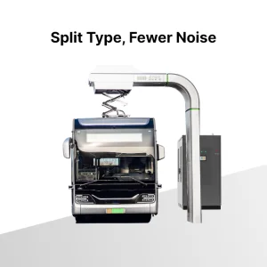
Comprehensive systems engineered for low noise, thermal resilience, and diverse localized application scenarios.
7kW to 22kW charging setups for workplace parking, residential complexes, and long-term public parking.
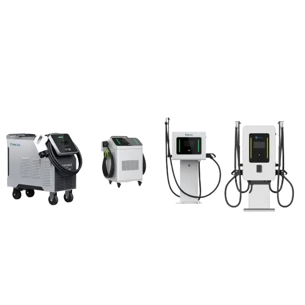
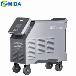
7kW, 20kW, 30kW, 40kW, 60kW, and 80kW mobile configurations for rapid depot service and emergency support.
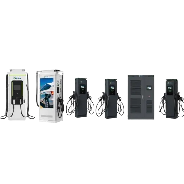
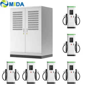
From 60kW-480kW floor-standing stations up to 360kW-1440kW split-type ultra-fast charging grids.
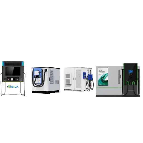
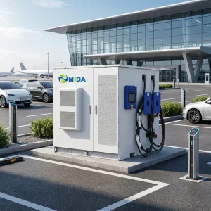
Integrated energy storage ranging from 60kWh up to 2MkWh systems to bypass strict local grid constraints.
Shanghai Mida Cable Group Ltd. operates through its wholly owned subsidiaries: Shanghai Mida EV Power Co., Ltd., Shenzhen Mida EV Power Co., Ltd., and Shanghai Mida New Energy Co., Ltd.
Mida Cable manufactures a comprehensive range of EV charging cables, including 16A–80A J1772 cables, 16A–63A IEC 62196-2 Type 2 cables, and DC fast charging cables: CCS1 (80A–500A), CCS2 (125A–1000A), CHAdeMO (125A–300A), GBT (200A–1000A), and NACS connectors (250A–600A).
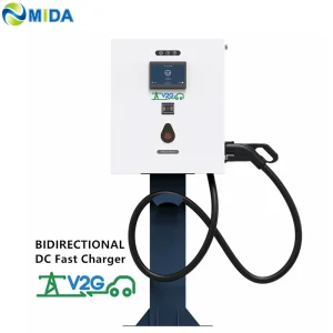
MIDA EV Power produces a full lineup of EV charging stations, such as 7kW–50kW mobile chargers, 3.6kW–7.2kW portable DC chargers, 360kW–1440kW split-type DC fast chargers, 20kW–50kW wall-mounted DC chargers, and 60kW–480kW floor-standing DC fast charging stations.
MIDA New Energy specializes in EV charger power modules, offering 20kW–60kW standard modules, 40kW–125kW liquid-cooled modules, 30kW–62.5kW bidirectional modules, and 20kW–45kW V2G charging modules.

Industrial component engineering for high-performance DC architectures.
Deploying a 360kW charger demands seamless alignment with regional standard systems. Hardware reliability starts with core safety certifications. In North America, UL 2202 (standard for DC fast charging equipment safety) and NFPA 70 (National Electrical Code) govern layouts. In Europe, CE marking, EMC directives (Class A for industrial environments, Class B for commercial areas), and regional grid codes dictate configuration options.
Modern charging infrastructure relies heavily on open software communication protocol standards. Using standard OCPP 1.6J and the newer OCPP 2.0.1, our chargers integrate with any third-party Central Management System (CMS) or billing network. Furthermore, the incorporation of ISO 15118 enables automated authentication through Plug & Charge, removing physical steps from the user transaction process.
Looking ahead, high-power DC fast charging will rely on modular design, high-frequency conversion technologies, and wider grid integration strategies. The traditional silicon-based diode rectifier is quickly being replaced by Silicon Carbide (SiC) Metal-Oxide-Semiconductor Field-Effect Transistors (MOSFETs). This material allows higher switching frequencies and reduced heat loss, helping power cabinets exceed 96% energy conversion efficiency.
Future development will see the expansion of Megawatt Charging Systems (MCS) designed for heavy-duty trucking networks, mining operations, and regional airport ground equipment. Bidirectional power transfer—Vehicle-to-Grid (V2G)—will turn parked vehicles into grid assets that provide load shaving and support during peak hours. High-power charging stops will transition from simple load nodes into active, localized microgrids.
Analysis, technical guidelines, and global trends in heavy commercial transport electrification.

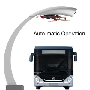
What are the advantages of an e-bus pantograph dome? In contrast to classic plug-in charging systems, e-bus pantograph networks offer higher uptime and speed...
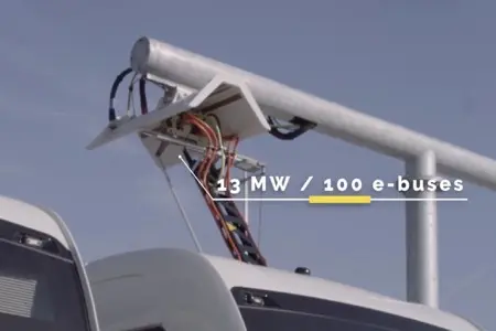
How long does it take to charge with an e-bus pantograph? The charging time depends on the battery capacity, state of charge, and the output capability of the cabinet...
How to Install the Pantograph Up Charger System Dome for Electric Bus. Installing a "Pantograph Up" system requires precise spatial alignment, structural support, and robust grounding...
Industrial parameters of the 360kW DC charging architecture.
Answers to common questions regarding integration, deployment, and operation of 360kW DC infrastructure.
Installing a 360kW system typically requires a 400V AC or 480V AC three-phase input supply. The transformer must accommodate the system's peak demand, plus accessory components. Depending on local grid codes, a dedicated substation or local battery storage buffer (BESS) can mitigate grid peak demands and lower connection fees.
Dynamic load balancing uses intelligent power distribution modules. When one vehicle is connected, the station delivers up to 360kW to that vehicle. When a second vehicle plugs in, the controller senses the demands of both vehicles and splits the capacity—such as 180kW+180kW, 240kW+120kW, or other configurations—to optimize charging speeds without overloading the system.
Air-cooled systems rely on high-capacity internal fans and are ideal for power cabinets running up to 200A. Liquid-cooled systems run coolant through the charging cables and connector contacts, enabling higher continuous currents (up to 500A or 600A). This makes liquid cooling necessary for continuous charging speeds above 250kW.
ISO 15118 enables "Plug & Charge" capabilities, where security certificates stored in the vehicle communicate directly with the charging station when connected. This authorizes the charge cycle and handles billing automatically, eliminating the need for external RFID cards, mobile applications, or credit card readers.
Industrial solutions designed for reliable performance in demanding environments.