
Explore our leading industry-grade charging infrastructure designed for extreme performance, compliance, and energy resiliency.

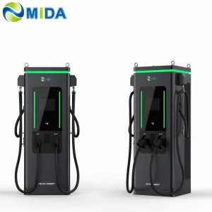
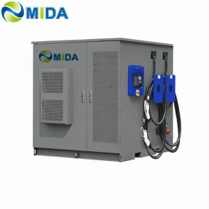
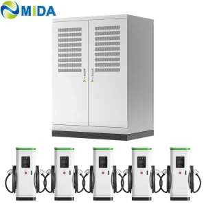
Max Output Power
Power Conversion Efficiency
Ready Protocol Standard
Liquid-Cooled Current

Comprehensive systems engineered to resolve modern charging, battery storage, and cable connector challenges.
Compact, Flexible Power Delivery
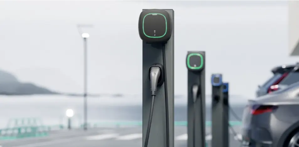
Supercharging & Megawatt Hubs
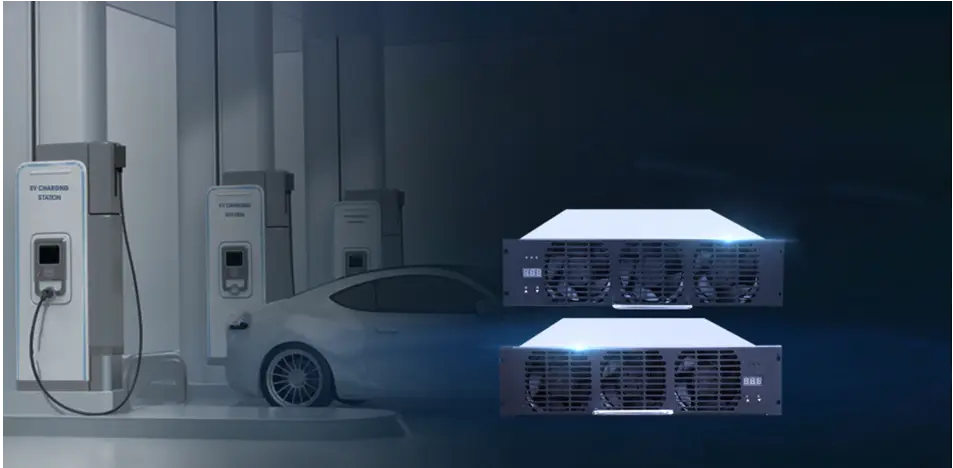
Smart Energy Buffer & Peak Shaving
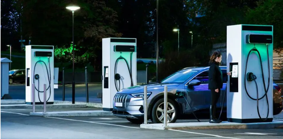
As fleet operators and public charge point operators (CPOs) ramp up electrification initiatives, traditional power systems are facing significant grid constraints. Fast car charging stations have transitioned from simple electrical points to complex cyber-physical grid components. Navigating this architecture requires a detailed understanding of converter topologies, cooling mechanisms, and energy buffer systems.
Modern ultra-fast charging systems (from 350kW to over 1MW) demand highly efficient power stage designs. High-frequency three-phase Active Front End (AFE) rectifiers, implemented with Silicon Carbide (SiC) MOSFETs, have replaced traditional silicon-based devices. SiC technology enables switching frequencies to exceed 50kHz, reducing converter footprints by 40% while maintaining conversion efficiencies above 97.5%. Mida Group’s dedicated power modules are engineered to optimize this switching process, minimizing losses even under extreme load demands.
Integrating ultra-fast chargers into existing utility lines often requires expensive substation upgrades. Microgrid architectures, combining Battery Energy Storage Systems (BESS) and photovoltaic (PV) generation, offer a viable alternative. By using a local 1MWh–2MWh battery reserve, charging facilities can cap grid consumption during peak hours, lower demand charges, and maintain stable 480kW outputs. This system also allows operators to participate in frequency regulation and peak-shaving programs, turning their stations into valuable grid assets.
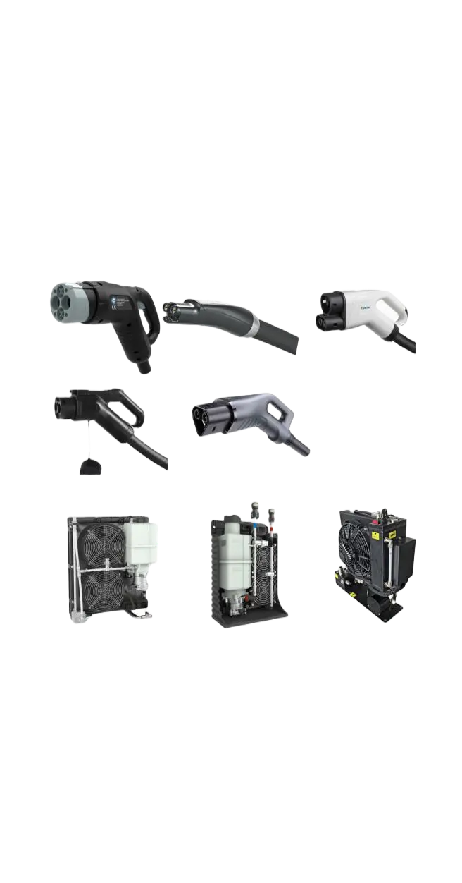
Continuous charging at currents above 200A generates significant thermal energy in the charging cable and connector. Without active cooling, cable diameters would become too heavy and inflexible for everyday users. Liquid-cooled systems circulate synthetic cooling oils or water-glycol mixtures through integrated cooling ducts inside the cable. This design supports currents up to 500A or 600A while keeping the cable lightweight and maintaining safe touch temperatures for operators.
Explore our underlying component technologies, high-power cables, and advanced power modules.
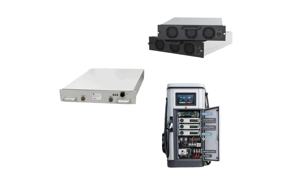
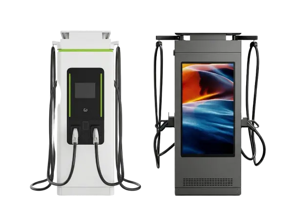
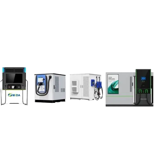
Deploying public fast charging infrastructure requires strict adherence to international safety, electrical, and communication standards. Without these certifications, operators risk liability issues, grid integration delays, and premature hardware failure.
Complete compliance with OCPP 1.6J and OCPP 2.0.1 ensures interoperability with all global back-end management networks. Dynamic load balancing allows remote management of station output based on local grid capacity.
Our stations are certified to CE, TUV, and UL standards. We support ISO 15118-20, which enables Plug & Charge technology and bi-directional energy transfer (V2G) between vehicles and the grid.
Units are housed in IP55 and IK10 enclosures, protecting against heavy rain, dust, and physical impact. Integrated cooling loops manage interior temperatures in climates ranging from -30°C to +50°C.
Stay up to date with the latest developments in transit fleet infrastructure and pantograph dome technologies.
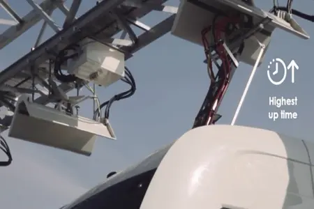
What are the advantages of an e-bus pantograph dome? In contrast to classic plug-in charging systems, e-bus pantographs enable automated overhead charging for transit networks.
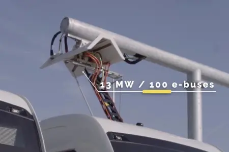
How long does it take to charge with an e-bus pantograph? The charging time depends on the battery capacity and the station output, typically taking 5 to 10 minutes for opportunity charging.
How to Install the Pantograph Up Charger System Dome for Electric Bus. Installing an overhead dome requires careful alignment, robust structural columns, and integration with local power lines.
Addressing the technical, operational, and commercial questions most relevant to charging point operators.
Reliable high-capacity charging units, split-system architectures, and battery-buffered stations.
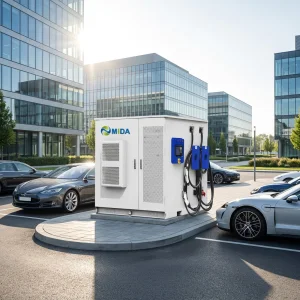
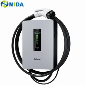
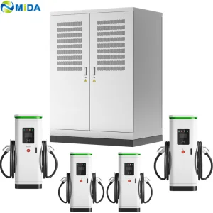
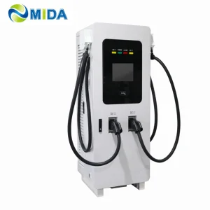
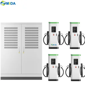
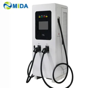
Connect with our expert application engineers to configure the optimal power stages, BESS integration, and cable setups for your specific site requirements.
Request Engineering Proposal