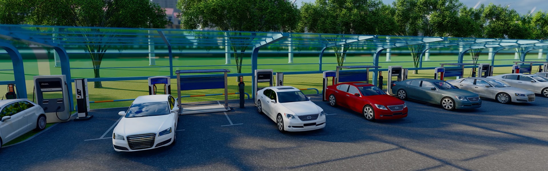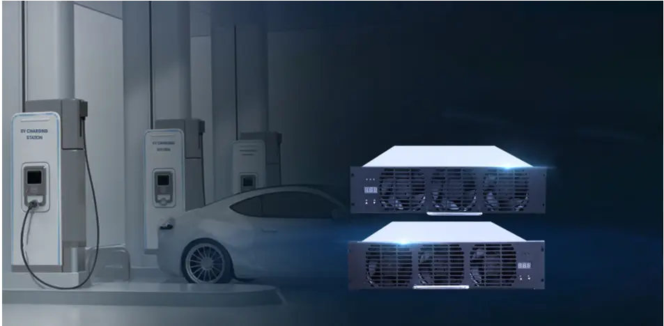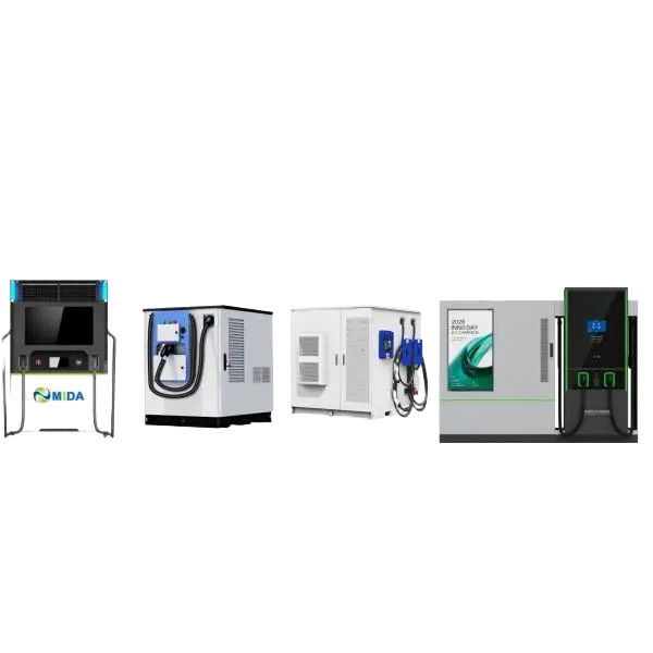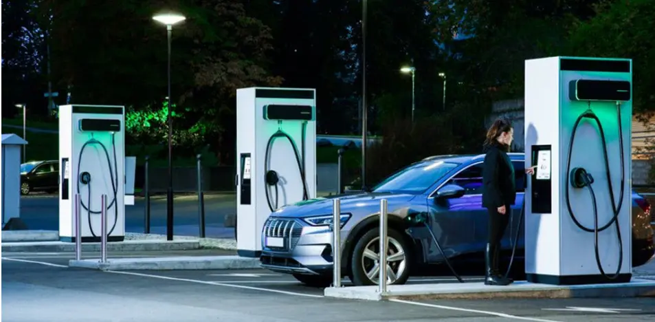
Explore our tier-1 engineering solutions, serving ultra-fast charging pathways and storage-backed grid balancing systems.
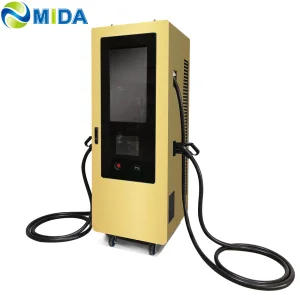
Decarbonization, High-Power Grid Integration, and Industrial Utility Solutions.
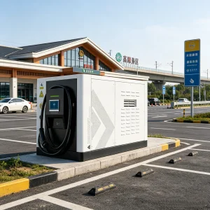
The global transition toward electrified fleet operations, public transit networks, and heavy-duty highway logistics has created unprecedented demand for reliable, utility-scale electric vehicle (EV) charging hardware. As municipal grids face distribution bottlenecks, the role of a modern EV Power Station Factory & Supplier extends far beyond basic mechanical assembly. Today’s infrastructure buyers—ranging from Charge Point Operators (CPOs) and national utility authorities to high-capacity commercial hubs—require complete energy portfolios featuring high-power charging dynamics, localized safety compliance, and integrated Battery Energy Storage Systems (BESS).
Procuring fast-charging infrastructure requires evaluating long-term Total Cost of Ownership (TCO) rather than simple initial capital expenditure (CAPEX). CPOs face critical operational realities such as peak-demand grid penalties, thermal degradation of modules, and international hardware interoperability. Leading factories leverage Silicon Carbide (SiC) semiconductor modules to achieve conversion efficiencies above 98%, directly reducing thermal load and power dissipation costs over a 10-year operating window.
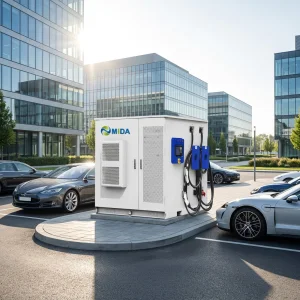
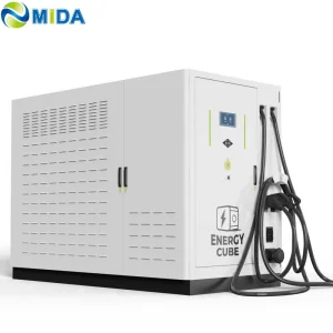
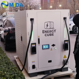
High-power DC charging stations exceeding 360kW represent significant load spikes for standard regional distribution grids. To avoid costly substation retrofits and demand charges, integrated Battery Energy Storage Systems (BESS) are essential. By storing energy during off-peak windows and discharging it during high-load EV connections, BESS-equipped stations enable stable megawatt-level charging on modest grid connections.
This hybrid architecture acts as a grid shock absorber. BESS charging systems with capacities from 60kWh to 2MWh allow facilities to implement peak-shaving, load-leveling, and local photovoltaic integration (solar-to-storage-to-charger loops). The result is a resilient, self-contained microgrid capable of delivering continuous high-current power without causing local voltage sags.
Shanghai Mida Cable Group Ltd. operates through its wholly owned subsidiaries: Shanghai Mida EV Power Co., Ltd., Shenzhen Mida EV Power Co., Ltd., and Shanghai Mida New Energy Co., Ltd. This division of roles allows us to maintain strict engineering focus across three core areas of electric vehicle supply equipment (EVSE):

Optimized hardware solutions across standard alternating current, high-voltage direct current, and storage-backed architectures.
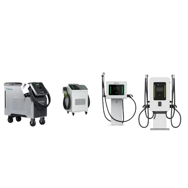
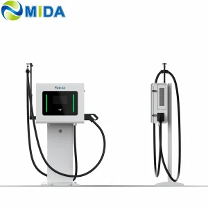
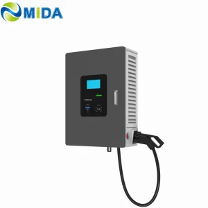
Wall-Mounted/Mobile EV Charger (7kW - 80kW)
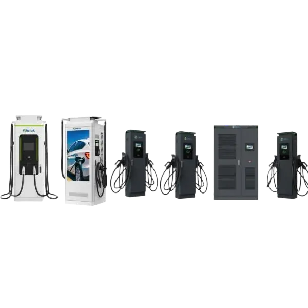
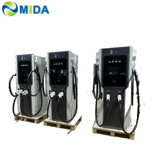
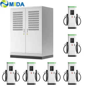
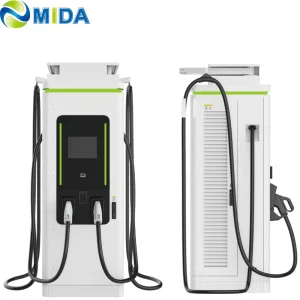
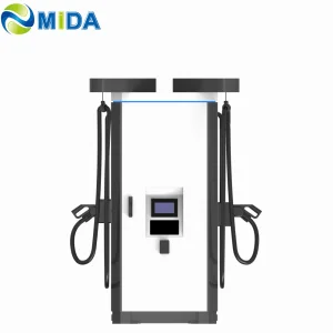
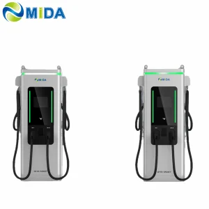
60kW - 480kW / 360kW - 1440kW Ultra-Fast Platforms
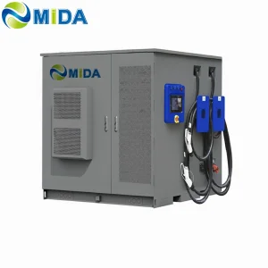
Battery Storage Integration: 60kWh to 2MWh
Detailed component and station configurations engineered for reliability, safety, and cross-platform compatibility.
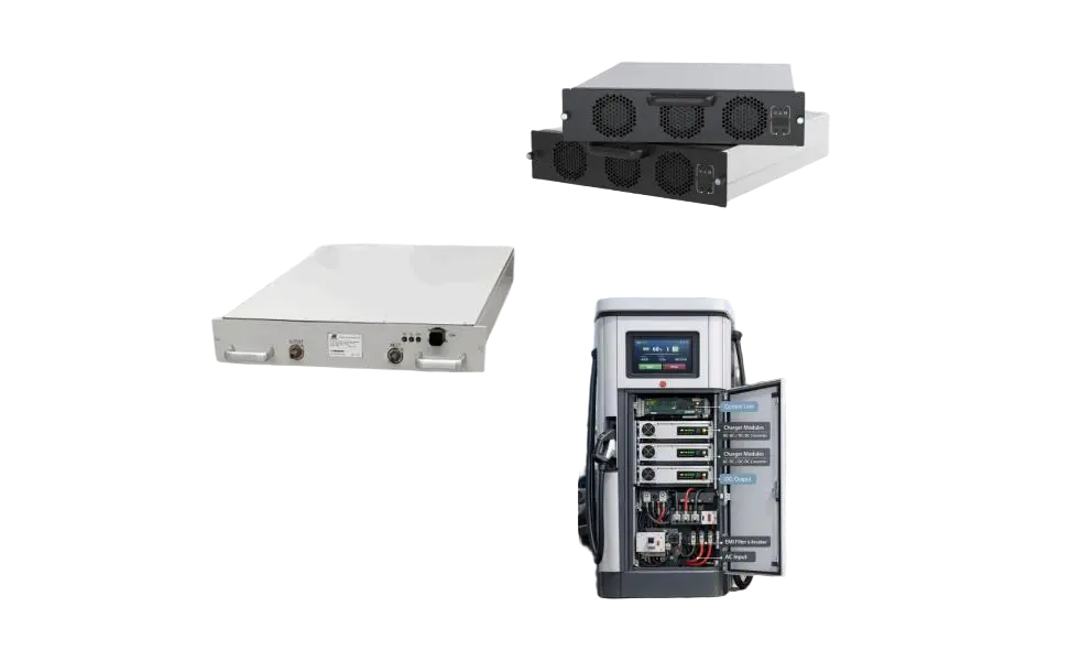
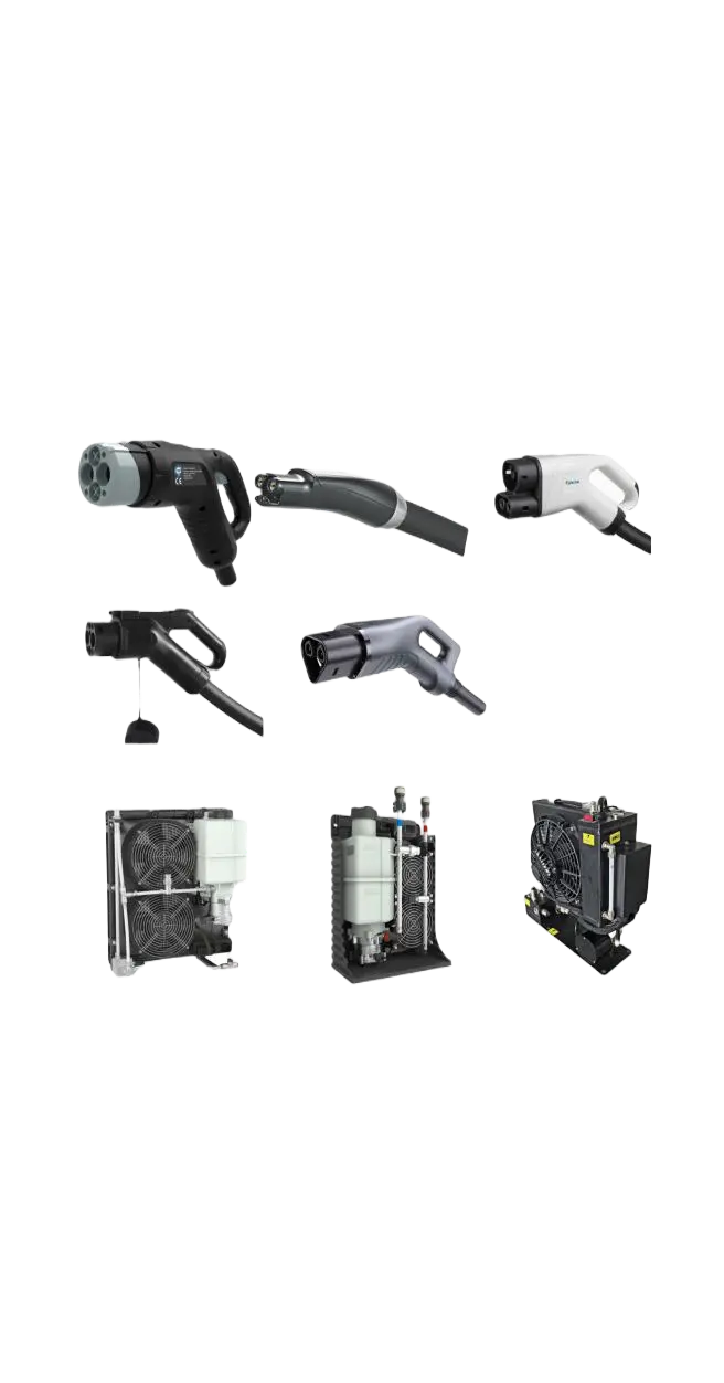
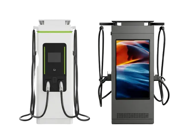
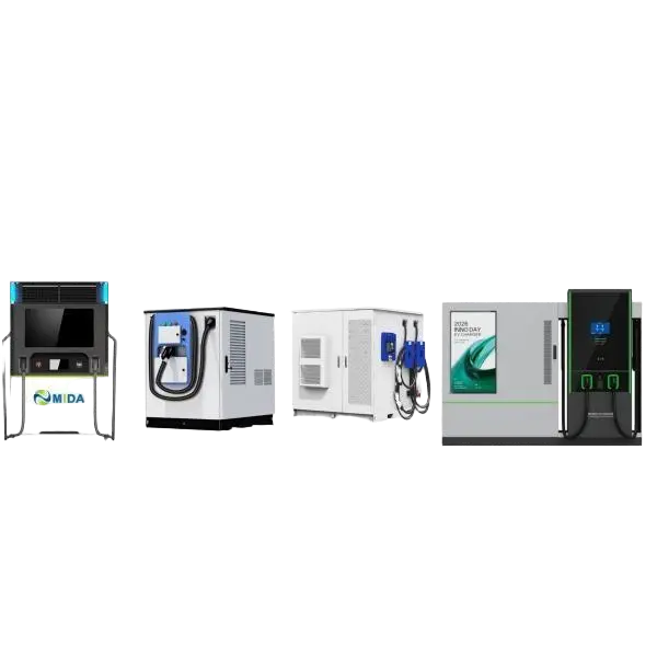
How MIDA ensures seamless integration with diverse utility grids, regional electrical standards, and software protocols.
To achieve output currents up to 600A without overheating, chargers must use active liquid cooling systems. By circulating non-conductive coolant through the charging cable and connector, we can maintain temperatures below 50°C. This prevents thermal throttle-back, ensures stable power delivery, and allows the use of thinner, lighter cables that are easier for drivers to handle.
Our split-type chargers dynamically route power in 20kW/30kW increments based on the vehicle's state of charge (SoC). When two vehicles connect to one cabinet, the charger balances the load to maximize throughput for both. This dynamic management reduces overall charging times and prevents grid spikes.
All stations support the Open Charge Point Protocol (OCPP 1.6J / OCPP 2.0.1 JSON API) for integration with third-party billing, management, and network systems. Hardware configurations meet global safety standards, including UL 2202, CE, CB, RoHS, and local grid codes (such as IEEE 1547 and VDE-AR-N 4105).
Technical updates from our engineering teams on public transit electrification, pantograph engineering, and depot layout.

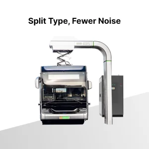
What are the advantages of an e-bus pantograph dome? In contrast to classic plug-in charging systems, e-bus pantograph domes enable automated, hands-free charging during layovers. These rooftop connection points support megawatt-level power transfers, helping municipal bus fleets maintain schedule reliability throughout the day.
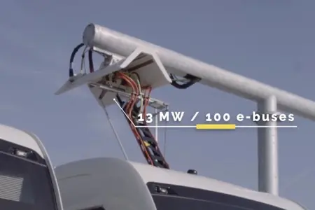
How long does it take to charge with an e-bus pantograph? Pantograph charging speeds depend on the vehicle's battery capacity and the station's configuration (typically 300kW to 600kW). A 10-to-15-minute layover charge can restore enough range for multiple route segments, reducing the battery capacity needed on the bus itself.
How to Install the Pantograph Up Charger System Dome for Electric Bus. Installing a "Pantograph Up" system requires precise alignment between the overhead charging station dome and the bus’s roof-mounted contact rails. Proper planning for structural supports, wind loads, and grid integration is essential to ensure long-term, reliable operations.
Select configurations for megawatt-level bus depots, microgrid storage, and remote high-voltage operations.
Detailed answers to key technical questions from CPOs, utility partners, and facility engineers.