Best EV Charger Supplier & Factory

Global Industrial Charging Stations, High-Power Liquid-Cooled Dispensing Systems, and Fully Integrated BESS Charging Infrastructure

3 +

Wholly Owned Subsidiaries

1000A +

Liquid Cooled CCS2/GBT

1680kW

Split Type DC Charging Limit

V2G & BESS

Smart Grid Ready Modules

Welcome to MIDA Group

Shanghai Mida Cable Group Ltd. operates through its wholly owned subsidiaries: Shanghai Mida EV Power Co., Ltd., Shenzhen Mida EV Power Co., Ltd., and Shanghai Mida New Energy Co., Ltd. This unified structure allows us to offer vertically integrated production capabilities from raw cable drawing to software integrations.

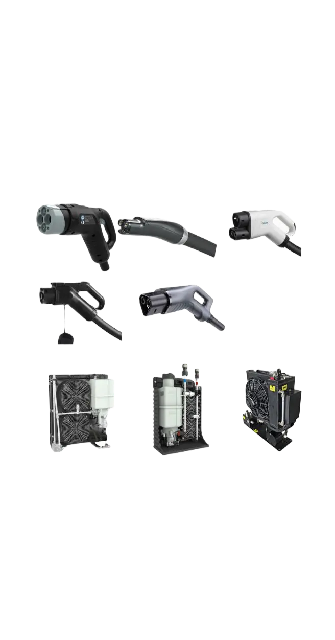
Mida Cable manufactures a comprehensive range of EV charging cables, including 16A–80A J1772 cables, 16A–63A IEC 62196-2 Type 2 cables, and heavy-duty DC fast charging cables: CCS1 (80A–500A), CCS2 (125A–1000A), CHAdeMO (125A–300A), GBT (200A–1000A), and NACS connectors (250A–600A).

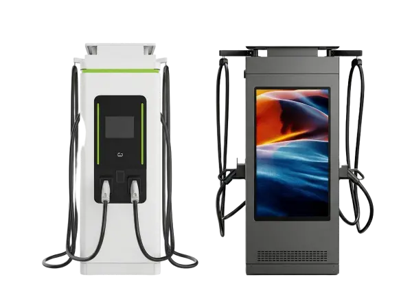
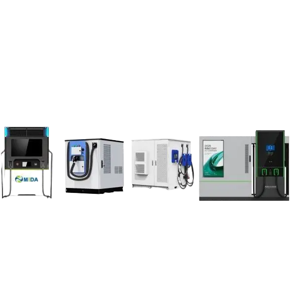
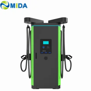
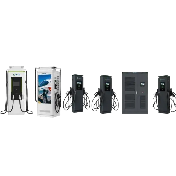
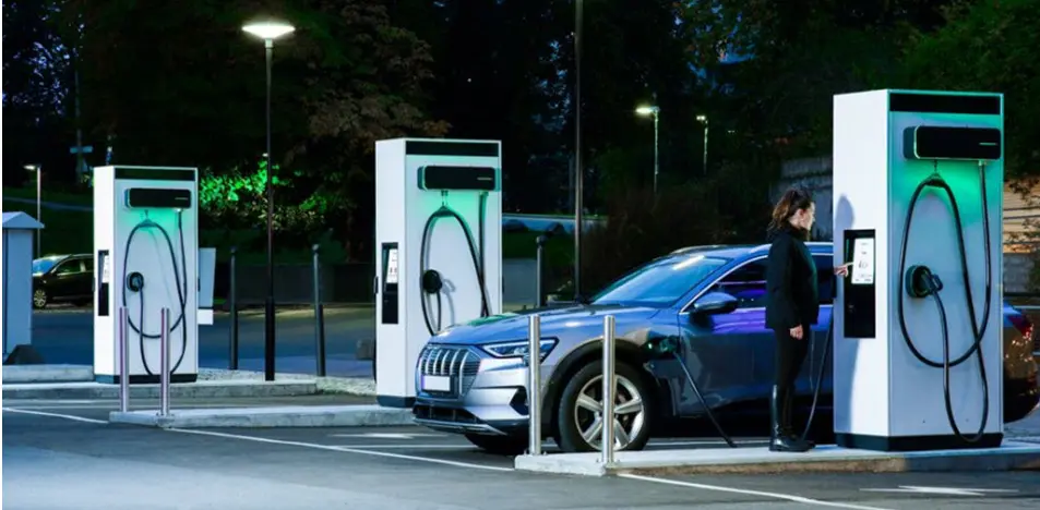
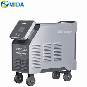
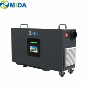
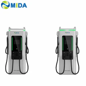
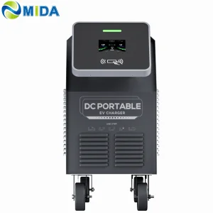
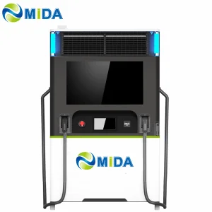
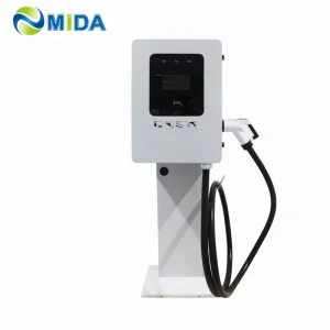
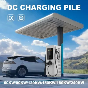
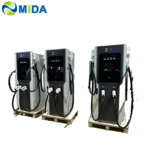
MIDA EV Power produces a full lineup of EV charging stations, such as 7kW–50kW mobile chargers, 3.6kW–7.2kW portable DC chargers, 360kW–1440kW split-type DC fast chargers, 20kW–50kW wall-mounted DC chargers, and 60kW–480kW floor-standing DC fast charging stations.

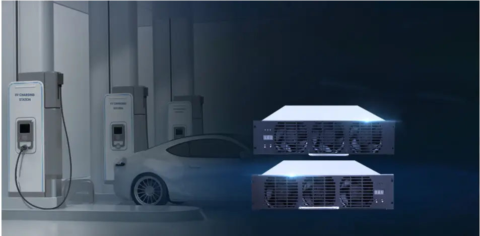
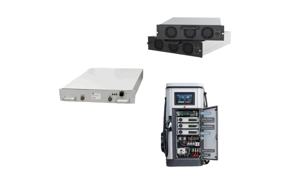
MIDA New Energy specializes in EV charger power modules, offering 20kW–60kW standard modules, 40kW–125kW liquid-cooled modules, 30kW–62.5kW bidirectional modules, and 20kW–45kW V2G charging modules.

MIDA Logo

Global Commercial & Industrial EV Charger Landscape

Insights into the infrastructure demands, utility interactions, and technical requirements shaping the global market.

The global transition to electric mobility is no longer driven solely by consumer passenger vehicles; it is increasingly defined by the electrification of commercial logistics, public transit systems, and corporate fleets. As regulatory bodies in North America (such as the NEVI program) and Europe (including the AFIR mandates) establish stricter charging corridors, commercial operators are facing unprecedented challenges in infrastructure deployment. High-power charging (HPC) networks demand stable, scalable, and highly efficient hardware capable of delivering continuous power under extreme conditions.

In industrial contexts, grid constraints are a primary bottleneck. Connecting multiple 180kW or 360kW DC charging piles directly to the local distribution network can lead to peak demand penalties and power instability. This has led to the adoption of Battery Energy Storage System (BESS) integration, where local batteries act as a buffer, storing power during off-peak periods and discharging it during simultaneous high-current charging sessions. Consequently, selecting an EV charger factory with native BESS-integration engineering capabilities is crucial for modern enterprise procurement.

"Successful global deployment depends on interoperability. Hardware must not only match physically with regional connectors (CCS1, CCS2, NACS, GB/T) but must also support deep integration via OCPP with local Charge Point Operators (CPOs) and grid load balancing tools."

Product Classifications & Solutions

A comprehensive overview of our standard hardware designs built for versatility and high efficiency.

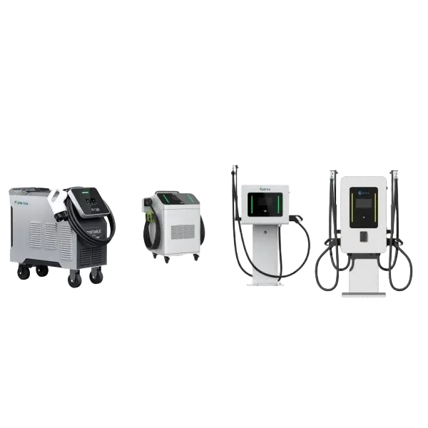
Wall-Mounted/Mobile EV Charger
7kW 20kW 30kW 40kW 60kW 80kW
Wall-Mounted/Mobile EV Charger
Details icon
Wall-Mounted/Mobile EV Charger
View More
DC Charger Station
60kW-480kW 360kW-1440kW
DC Charger Station
Details icon
DC Charger Station
View More
BESS Charging Station
60kWh 261kWh 418kWh 625kWh 2MkWh
BESS Charging Station
Details icon
BESS Charging Station
View More

China Factory Efficiency Advantages & Technical Supremacy

How manufacturing clustering and vertical integration enable superior cost performance and engineering agility.

The concentration of raw material sourcing and sub-component manufacturing within China creates an unparalleled ecosystem for producing high-power EVSE. Unlike fragmented supply chains in other regions, a Chinese factory typically operates in close proximity to major producers of power semiconductor modules (such as IGBTs and SiC devices), high-frequency transformers, liquid cooling units, and electronic control relays. This close integration drastically minimizes logistics lead times and facilitates seamless R&D cooperation during custom prototype developments.

Additionally, the scaling capability of Chinese manufacturing plants translates to significant cost efficiencies. Highly automated assembly lines, computerized SMT operations, and dedicated environmental testing chambers ensure that large-scale orders are completed with consistent quality control metrics. Burn-in tests, insulation resistance verification, and high-temperature operating tests are performed at scale, reducing the Field Failure Rate (FFR) of the charging modules. For enterprise procurement managers, this combination of cost efficiency, rapid scaling, and strict quality control minimizes initial capital expenditure while ensuring long-term hardware reliability.

Main Products Directory

A closer look at MIDA Group's structural component catalogs and customized options.
EV Charging Power Module

  • 30kW 40kW 50kW 60kW 80kW AC DC EV Charger Module
  • 30kW 40kW 50kW 60kW DC DC EV Charger Module
  • 40kW 60kW 75kW 125kW Liquid Cooled Power Module
  • 20kW 22kW 30kW 40kW 45kW V2G Power Module
  • 30kW 40kW 50kW 60kW MPPT Power Module
  • 20kW 50kW 62.5kW Bidirectional AC DC Power Module
EV Charging Power Module
View More

DC Charging Connector & Liquid Cooling Unit

  • 500A 600A CCS1 & CCS2 & GBT Connector
  • 125A 250A 300A 350A NACS & CHAdeMO Connector
  • 1500A MCS Connector & CHAOJI Connector
  • 3.5kW 4.5kW 6kW 9kW Integrated Liquid Cooling Unit
  • 2.4kW 3.5kW Split Type Cooling Unit
  • 25kW ~72kW Cooling Unit for HPC Charging
DC Charging Connector
View More

DC Fast Charger Station

  • 7kW~ 60kW Mobile DC Charging Station
  • 20kW ~80kW Wall Mounted DC Charging Station
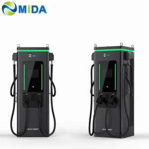
  • 60kW ~480kW Floor Mounted Charging Station
  • 60kW~240kW Advertising Charging Station (43inch , 55inch )
  • 600kW ~1080kW Liquid Cooled Charging Station
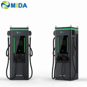
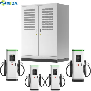
  • 360kW ~ 1680kW Split Type DC Charging Station
DC Fast Charger Station
View More

Energy Storage Charging Station

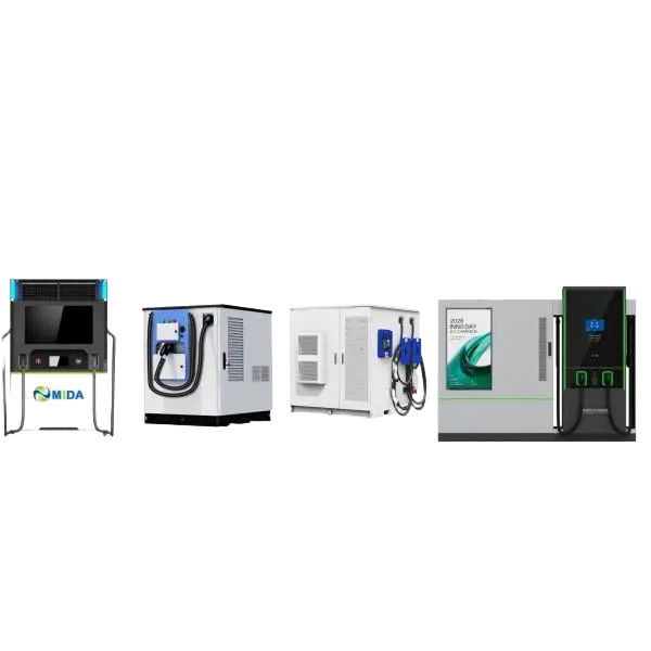
  • 15kW~480kW Mobile ESS Charging Station
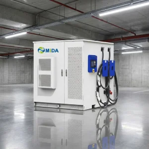
  • 60kW ~ 400kW Integrated ESS Charging Piles
  • 65kWh~200kWh Emergency Rescue Charging Station
  • 165kwh Automatic Charging Robot
  • 800kwh~2000kwh Solar Energy Charging System
Energy Storage Charging Station
View More

Localized Applications & Operational Scenarios

Deploying charging hardware requires understanding the environmental and operational dynamics of each deployment site:

  • Commercial & Public Fleet Depots: Delivery fleets, municipal utility trucks, and electric buses need reliable, scheduled power. Deploying 60kW to 180kW dual-gun chargers with smart dynamic scheduling algorithms ensures vehicles are fully charged by departure time without overloading local substation limits.
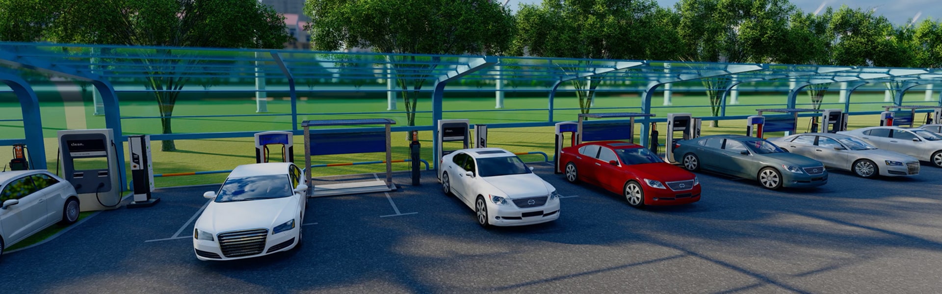
  • Highway Service Stations: High throughput is the primary goal here. High-power split chargers (360kW to 1680kW) paired with liquid-cooled cables allow drivers to recharge up to 80% capacity within 10 to 15 minutes, maximizing driver turnaround.
  • Destination & Workplace Parking: Where vehicles remain parked for 4 to 8 hours, AC EV Chargers (7kW to 22kW) or lower-capacity wall-mounted DC fast chargers (20kW to 30kW) provide a balanced load distribution and reduce utility costs.
  • Remote and Off-Grid Sites: BESS-integrated solar charging stations offer an independent power network. By combining PV generation with dynamic battery storage, these systems support high-power DC fast charging in regions lacking medium-voltage grid access.

Future Engineering Trends in the EVSE Industry

As battery technologies advance, the charging infrastructure must keep pace. The industry is currently shifting toward:

  • Wide Voltage Ranges (Up to 1000V DC): Newer EV platforms are adopting 800V architectures to decrease charging times and cable thickness. Standard charging power modules must support wide output voltages (from 150V to 1000V) to remain backward-compatible with legacy 400V battery systems.
  • Megawatt Charging Systems (MCS): Designed specifically for maritime vehicles and class 8 heavy-duty vehicles, MCS targets charging capabilities of up to 3.75 Megawatts, requiring specialized connectors and closed-loop liquid thermal cooling systems.
  • V2G and Bidirectional Operations: Transitioning vehicles from simple power sinks into dynamic grid assets. Bidirectional modules (AC-DC/DC-AC) allow fleet operators to feed power back into the grid during peak pricing windows, offsetting operating costs.

Corporate News & Technical Insights

Stay informed about our latest technical articles and installation guides.
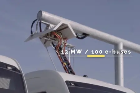
e-bus pantograph dome

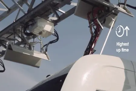
Advantages of an E-Bus Pantograph Dome

In contrast to classic plug-in charging systems, e-bus pantograph networks offer automated connection, high power throughput, and hands-free charging, minimizing physical labor and bay idle times.
Date: 26-07-12 View More
Pantograph charging speed

Charging Times via Pantograph Units

Charging time depends directly on internal battery capacity and actual power output. Mega-amp dynamic interfaces can achieve full transit fleet recharges in less than 20 minutes.

Date: 26-07-12 View More
Install Pantograph Up Charger

Installing "Pantograph Up" Charger Systems

A detailed guide on site preparation, structural integrity requirements, alignment tolerances, and safety clearances for setting up e-bus dome systems.

Date: 26-07-12 View More

Technical FAQ & Hardware Procurement Guidelines

Detailed explanations regarding compliance, safety features, and configuration parameters.

Q1: What are the primary differences between OCPP 1.6J and OCPP 2.0.1 for high-power DC stations?
OCPP 2.0.1 offers significant security and operational improvements over OCPP 1.6J. Key updates include enhanced device management (allowing real-time diagnostics and advanced configuration profiles directly from the central management system), native support for ISO 15118 (enabling Plug & Charge and smart charging operations), and improved message packaging using JSON over WebSockets to optimize cellular communication.
Q2: How do liquid-cooled charging cables achieve currents up to 1000A without overheating?
Standard air-cooled charging systems are limited to approximately 250A-300A due to thermal dissipation constraints and cable weight limits. Liquid-cooled systems circulate synthetic coolant or a water-glycol mixture through internal tubes directly adjacent to the copper conductors. This design continuously extracts heat, allowing the cable to maintain a safe working temperature while carrying up to 1000A in a flexible, lightweight profile.
Q3: Why is a wide output voltage range (150V - 1000V) important for new installations?
Older passenger electric vehicles generally operate on 400V platform designs. However, newer vehicles are transitioning to 800V architectures to decrease charging times. A charging station that supports a wide output voltage range (150V to 1000V DC) ensures compatibility with both standard 400V vehicles and high-voltage 800V battery platforms without requiring hardware upgrades.
Q4: What role do BESS charging stations play in locations with grid limitations?
BESS (Battery Energy Storage System) charging stations integrate local batteries to manage demand spikes. During low-demand periods, the system charges the internal batteries from the grid or solar PV panels. When a vehicle initiates a high-power charging session, the system draws energy from the battery pack to supplement grid power, avoiding demand charge penalties and allowing for fast charging even on restricted local grids.
Q5: What safety certifications should a global enterprise require when purchasing chargers from China?
For European markets, hardware must bear the CE mark, indicating compliance with the Low Voltage Directive (LVD) and Electromagnetic Compatibility (EMC) standards, ideally certified by independent testing laboratories like TÜV. For the North American market, UL 2231-1/-2 and UL 2594 listings are essential to ensure compliance with local electrical safety regulations.
Q6: How does dynamic power allocation work in split-type DC charging stations?
Dynamic power allocation uses a centralized matrix switch to assign power module capacity to individual charging ports based on real-time demand. For example, if a single vehicle is charging, the system can route the full output of multiple modules to that port. If additional vehicles connect, the system automatically redistributes the modules to deliver the optimal charge rate for each connected vehicle, maximizing overall system efficiency.
High-Power EV Charging Infrastructure Operations